Protected topology will result in having a better association between the mesh topology (nodes, faces, elements) and the geometry features (topology).That is,
A geometry vertex should have a node associated to it.
A geometry edge should have mesh nodes/edges associated to it.
A geometry faces should have mesh nodes/faces/elements associated to it.
A geometry body should have mesh nodes/elements associated to it.
Since boundary conditions are ultimately applied to the mesh, it is important to have proper associations to get proper loading. Thus, if protected topologies are ignored, an error or warning message may be issued by the mesher.
There are two levels of topology protection, namely hard and soft.
Hard protected topology can be defined by scoping Named Selections and/or Contact region objects to geometry (bodies, faces, edges, and vertices) and setting the Protected option to Yes. This instructs the mesher to give higher priority to those geometry features. Thus, during mesh generation, the outer boundaries of a collection of hard protected topologies will be maintained. The mesher will return an error state and message if the outer boundaries of the hard protected topologies cannot be protected.
Soft protected topology can be defined by scoping Named Selections to geometry (bodies, faces, edges, and vertices) and setting the Protected option to Program Controlled. For soft protected topologies, mesh-based defeaturing takes priority. Thus, the outer boundaries of soft protected topologies may be altered by the mesher. In such situations, mesher will return a warning message. You can right-click the warning message and use the Show Problematic Geometry option to visualize problematic geometries. You should verify that the mesh is acceptable in case of defeaturing of outer boundaries of the soft protected topologies.
Setting up Hard Protected Topology
For contacts, set Protected to Yes.
For Named Selections, set Protected to Yes.
Setting up Soft Protected Topology
For Named Selections, set Protected to Program Controlled. When Program Controlled is selected, the scoped object(s) will be considered as soft protected. The scoped objects will not receive additional protection by the mesher, even if the Named Selection is used for boundary conditions, symmetry, other types of loads for the solver, as well as match controls and hard sizing controls for meshing. Mesh-based defeaturing will have priority and the outer boundaries of these topologies may be altered by the mesher.
Resuming Legacy Databases (prior to Release 19.0)
If you resume a legacy database (prior to Release 19.0) with protected topologies:
Contacts are resumed with Protected set to No.
Named selections are resumed with Protected set to Program Controlled.
Note:
If surface bodies have differing thicknesses, the edges between the faces will be protected unless using MultiZone Quad/Tri mesh method. If using the MultiZone Quad/Tri mesh method, use Preserve Boundaries = All, or put the faces into separate named selections.
If you use the MultiZone mesh method and set Preserve Boundaries to All, the MultiZone method will protect all boundaries.
Virtual Topology can still be used with patch independent meshing; however, the boundaries of the virtual cells do not have to be protected unless the virtual topology is scoped to something. In other words, the virtual cells replace the underlying geometry but follow the same protection rules.
You should apply loads/boundary conditions prior to meshing as it is the most robust process to get the proper mesh to respect the boundary conditions.
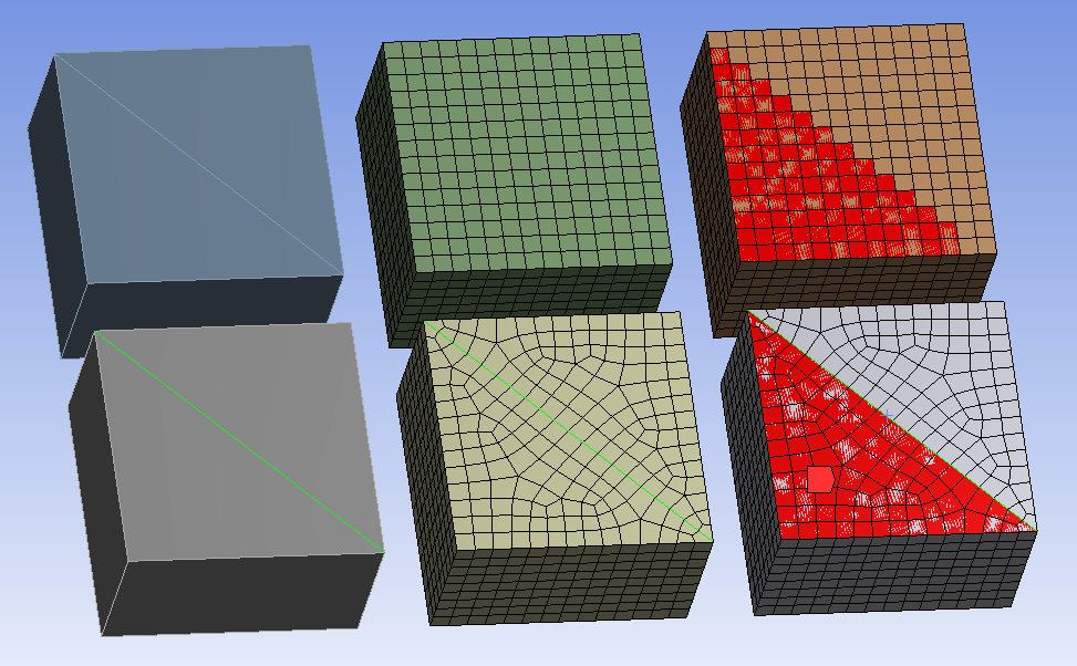
The mesh is associated to the geometry even for bodies, faces, edges, and vertices that are not protected, but in such cases there may not be the one-to-one relationship that exists between the mesh and geometry for protected topology. For example, in Figure 68: Protecting Topology the highlighted edge is protected for the boxes in the bottom row, but not for the boxes in the top row.
In the two boxes on the right, the faces with red mesh indicate face mesh that is associated with the triangular face on the left of the geometry. Due to the sharp features of the box, the side faces all have a one-to-one relationship. You can check the association by using the Plot Elements Attached to Named Selections option.