


Manages imported cross sections. The application automatically generates cross section objects when you import a line body that includes cross sectional data. For each imported cross section, there is an associated cross section object that displays the cross section type specified in a CAD application as well as via External Model. These objects are contained in the Cross Sections folder and provide data for the associated CAD cross section specifications of your imported line body. You can modify cross section Dimension values in the Details of the object(s).
Important: The application cannot complete the solution process if one or more cross sections share the same name and will display an Error message when duplicate names are encountered. You can manually change the names (in your CAD application or in Mechanical) or use the context (right-click) menu option to have the application change the duplicate names. Also note that, if you are using Model-to-Model linking, Ansys recommends that you set the Workbench Project page Object Renaming property accordingly.
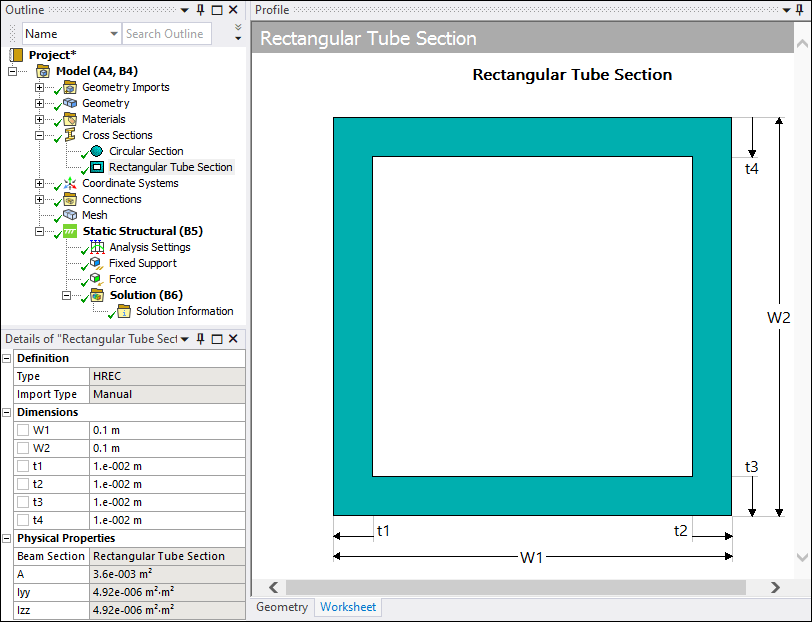
And as illustrated below, you can use the options of the Cross Section Context menu to manually define cross sections. Included with the context tab options is a Profile option. This option displays a window that enables you to view the cross section dimensions as you make entries and upon completion.
Note: You may wish to review the SECTYPE and SECDATA commands. These commands send cross section data to the MAPDL solver.
 |
Object Properties
The Details Pane for this object includes the following properties.
| Category | Properties/Options/Descriptions | |||
|---|---|---|---|---|
|
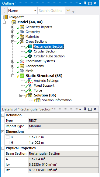
Definition |
Type: Displays the Element type used by the cross section. Import Type: Displays whether the cross section was imported or defined manually. | |||
|
Dimensions |
The various Dimensions properties (R, B, H, etc.) are based on your selected cross section type. See the Cross Section Types section as well as the individual cross section type sections of the Ansys DesignModeler User's Guide for more information about dimensions. Also refer to the SpaceClaim Direct Modeler documentation for additional cross section information.
| |||
|
Physical Properties |
The Physical Properties category provides the following read-only properties that display the associated cross section information provided by the upstream system (that is, CAD application/External Model system):
Note: DesignModeler uses a different cross section coordinate system than Mechanical (MAPDL solver). Mechanical displays Izz whereas DesignModeler displays Ixx. In DesignModeler, the cross section lies in the XYPlane and the Z direction corresponds to the edge tangent. In the Mechanical environment, the cross section lies in the YZ plane and uses the X direction as the edge tangent. This difference in orientation has no bearing on the analysis.
See the Cross Section Types section of the Ansys DesignModeler User's Guide for additional information about these properties. You can also refer to the SpaceClaim Direct Modeler documentation for additional cross section information. |
Tree Dependencies
Valid Parent Tree Object: Cross Sections.
Valid Child Tree Objects: Not applicable.
Insertion Methods
The application automatically inserts available imported cross sections. You can also manually insert and define cross section objects.
Right-click Options
In addition to common right-click options, relevant right-click options for this object include:
> [available types of cross sections]
API Reference
See the Cross Section section of the ACT API Reference Guide for specific scripting information.
Additional Related Information
Cross Section (Ansys DesignModeler User's Guide)