|
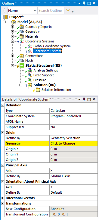
Definition
|
- Type
Options include and
. - Coordinate System
Options include and
. They assign the coordinate system reference number automatically or
manually. If you specify , the
Coordinate System ID property displays. Enter a value
greater than or equal to 12. Coordinate systems must have a unique ID. - APDL Name
When using the Mechanical APDL solver, this text-based field enables you to
create an APDL parameter (in the input file) and assign its value to the
reference number of the coordinate system. This facilitates easy programmatic
identification of the coordinate system for later use/reference in a Command
object. - Suppressed
Options include and
(default). Suppressing a coordinate system
removes the object from further treatment, and writes no data to the input
deck, and causes any objects scoped to the coordinate system to become
underdefined (therefore invalidating solutions).
|
|
Origin
|
- Define By
Options include (default),
, and . - Geometry
When the Define By is set to Geometry Selection, this property displays. You use this property
to select geometry or mesh entities that define the origin of the Coordinate
System. - Named Selection
When the Define By is set to , this property displays. Select a user-defined Named
Selection. - Origin X
Enter an X location on the coordinate axis from the (0, 0, 0)
location. - Origin Y
Enter a Y location on the coordinate axis from the (0, 0, 0)
location. - Origin Z
Enter a Z location on the coordinate axis from the (0, 0, 0)
location. - Location
Visible when the Define By property is set to
. You can specify the property by: Selecting geometric entities (vertex, edge, or face). Selecting mesh entities (Node, Element Face, or Element) Using the Hit Point Coordinate option on the
Graphics Toolbar.
|
| Principal
Axis |
- Axis
Options include: ,
, and . This property
defines the Principal Axis vector with respect to one of these planes. - Define By
Property options include: | Geometry Selection | | Fixed Vector | | Global X Axis | | Global Y Axis | | Global Z Axis | | Hit Point Normal |
|
|
Orientation About Principal
Axis
|
- Axis
Based on the Principal Axis settings above, define the Orientation About
Principal Axis vector with respect to the X, Y, or Z plane. - Define By
Property options include: | Default | | Geometry Selection | | Global X | | Global Y | | Global Z | | Fixed Vector |
|
|
Directional Vectors
|
- X Axis Data
A read-only mathematical representation, in matrix form, showing of the X
vector orientation in space. - Y Axis Data
A read-only mathematical representation, in matrix form, showing of the Y
vector orientation in space. - Z Axis Data
A read-only mathematical representation, in matrix form, showing of the Z
vector orientation in space.
|
|
Transformations
|
- Base Configuration
Read-only property - . - Transformation Features
The following properties can be added to the active coordinate system
object from the Coordinate System
Context. They change the location and rotation of the original
definition of the coordinate system. These properties are order-dependent and
that order may be modified using the Move Up and
Move Down features of the Coordinate System
Context. | Offset X | | Offset Y | | Offset Z | | Rotate X | | Rotate Y | | Rotate Z | | Flip X | | Flip Y | | Flip Z |
- Transformation Configuration
Read-only property that displays the transformed coordinate point
locations from the origin.
|