


Introduction
For an appropriately modeled geometry, Mechanical provides options to specify reinforcements within a structure. Mechanical can model these reinforcing geometries with specialized reinforcing elements. These reinforcing elements provide extra reinforcing by interacting with the standard structural or thermal elements, referred to as base elements, via the shared nodes.
This section examines:
Feature Overview
Reinforcement is supported for the following three-dimensional analysis types:
Static Structural
Steady-State Thermal
Thermal-Stress (Steady-State Thermal linked to Static Structural)
Modal (Standalone and Pre-Stressed)
Harmonic Analysis (Standalone, Pre-Stressed, and MSUP)
Random Vibration
Response Spectrum
These analyses require that your imported model already include the line or surface bodies you wish to specify as reinforcements as well as an appropriate material to assign to these reinforcement bodies.
As illustrated, Mechanical provides reinforcement specification for line bodies (discrete reinforcing) and surface bodies (smeared reinforcing). Each line body specified as reinforcement basically represents a reinforcing fiber arbitrarily oriented in space. Each surface body specified as reinforcement basically represents a reinforcing layer. This reinforcing layer can be either a homogeneous reinforcing layer (membrane) or reinforcing layer with evenly spaced fibers.
| Discrete (Line Bodies Only) | Smeared (Surface Bodies Only) |
 |
 |
Mechanical uses the Mechanical APDL-based Mesh-Independent Method for Defining Reinforcing to create reinforcing elements. The mesh-independent method uses MESH200 elements to represent the reinforcing member locations inside the generated reinforcing elements.
When the solution is initiated, the application temporarily defines the reinforcement locations using MESH200 elements along with the base elements. During the solution process, the application internally creates the element REINF264 for line bodies or the element REINF265 for surface bodies based on the intersection of corresponding MESH200 and base elements.
Important:
The line and surface bodies defined as reinforcements are reinforcement representations, not actual reinforcing elements or members created by the MAPDL solver.
Different solver units might affect the number of reinforcing elements or members generated during the solve due to tolerances. This could lead to small differences in the result values.
Application
The steps to specify line or surface bodies as reinforcements include:
- Line Bodies
For the Line Body object:
Select the option for the Model Type property.
As needed, assign a material to the Line Body reinforcement.
Verify that the desired cross section is specified in the Cross Section property. The area value of this cross section is sent to the solver (Area property of the corresponding cross section object).
Note:The solver does not consider the shape of the cross section. The area of the cross section is the only required value. See the Reinforcing topic in the SECDATA command section of the Mechanical APDL Command Reference for more information.
During the solution process, by default, the application 1) turns on Tension and Compression and 2) removes the base material from the space occupied by the reinforcing fibers.
Repeat the above steps for all line bodies to be used as a reinforcement.
- Surface Bodies
For Surface Body objects, the default setting for the Model Type property is . The setting treats the body as a surface body - there is no reinforcement treatment.
To specify the Surface Body as a reinforcement:
Select the option for the Model Type property.
As needed, assign a material to the Surface Body reinforcement.
When you select the option, an additional property, Homogeneous Membrane, displays.
If the Homogeneous Membrane property is set to (default), then the Surface body is treated as a homogeneous reinforcing layer (membrane) in a plane-stress state. Verify the value in the Thickness property since this value is used for defining the cross section area of the reinforcing membrane inside the reinforcing element.
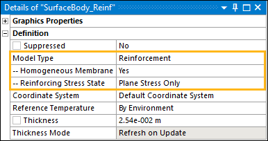
For 3D Structural analyses, when the Homogeneous Membrane property is set to , the additional property Reinforcing Stress State displays. This property enables you to specify the reinforcing stress state and stiffness behavior of the homogeneous reinforcing layer (membrane). Options include (default), , and . See the Reinforcing topic in the SECCONTROL section of the Mechanical APDL Command Reference for more information.
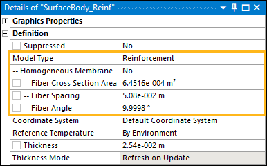
If Homogeneous Membrane property is set to , then the Surface Body is treated as a reinforcing layer with a cluster of parallel and equidistant fibers having the same cross section. This means that the layer has a uniaxial-stress state in the direction of the fibers. The value in the Thickness property is ignored. The following additional properties display and require specification:
Fiber Cross Section Area: Cross section area of the fiber.
Fiber Spacing: Distance between fibers.
Fiber Angle: Orientation of the associated fibers in the specified coordinate system.
In addition, select the appropriate Coordinate System to define the specific orientation of the fibers. See Element Coordinate System description in the MESH200 element section for more information.
Repeat the above steps for all surface bodies to be used as a reinforcement.
Note: During the solution process, by default, the application 1) turns on Tension and Compression when the Homogeneous Membrane property is set to No (uni-axial stress state) and 2) removes the base material from the space occupied by the reinforcing layer.
Loading Condition Specification
Only an Internal Heat Generation load or an Imported Heat Generation load can be applied to the bodies specified as Reinforcements.
Post Processing
You can create results for reinforcement bodies through Geometry Selection or using Named Selections. You can select specific reinforcement bodies or use the default setting of and hide appropriate base bodies to view the results on the reinforcements.
Because the solver generates reinforcing elements, only body-based results are available on the reinforcement bodies. Mechanical does not allow Face/Edge/Vertex/Node/Element/Element Face based results on Reinforcement bodies.
Also, if you mix reinforcement body selections with non-reinforcement body selections for your result scoping, the application displays results for the bodies that are not specified as Reinforcements and excludes the evaluation of results on the Reinforcement bodies.
Note: If you set the Scoping Method property to , the property displays for results on a specified set of reinforcing members. This corresponds to the global identifier (EGID) in Mechanical APDL.
Requirements and Limitations
Note the following when performing this analysis type:
Reinforcement is supported for 3D Static Structural and Steady-State Thermal analyses.
If you are using Material Assignment objects, Ansys recommends that you use separate Material Assignment objects or Line bodies and Surface bodies modeled as Reinforcements as well as for any non-reinforcement bodies. This helps ensure the application properly plots result data.
If you have assigned a material to the base body that does not support a 1D stress state, such as Drucker Prager, the application does not remove the base material in the space occupied by reinforcing members that have uniaxial stress state.
If you have a result object selected, certain mesh-based features are not available for the reinforcement elements of the geometry, including mesh selection filters (nodes, elements, and element faces), as well as the ability to display a Node ID in the probe label, and Selecting Nodes and Elements by ID.
Reinforcements do not support bending for nonhomogeneous membranes.
Thermal analyses do not support surface and line bodies as base bodies for creating reinforcing elements.
Reinforcement bodies do not support Remote Points, Symmetry, Fracture, or Connections. These features are ignored when scoped to reinforcement bodies.
Condensed Parts are not supported when a model contains reinforcements. If present, you can suppress the Condensed Part(s) or Reinforcement bodies in order to proceed with the solution.
Only Body-based results are supported for Reinforcement Bodies. (See the Post Processing topic above)
Reinforcements do not support and results.
For nodal results, such as nodal Reactions, that are scoped to reinforcement elements, the application displays values that are extrapolated, via shape functions, to element intersection points (II, JJ, etc.). This is also the case if you export result values. Exported result values may contain node numbers, but the result values are the interpolated intersection values. In addition, the summation of Mechanical nodal reaction results may not match those of the Mechanical APDL application.
For element nodal Reactions force results on reinforcement elements, the application only displays a subset of nodes on the result as compared to Mechanical APDL. For example, MAPDL lists 20 nodes for a smeared reinforcement element whereas Mechanical only lists four nodes. This also applies to exported result values.