


While setting up your simulation, you can use the Part Transform feature to modify the orientation of parts on your model. This can be beneficial if you want to reorient or move certain parts after they have been imported into Mechanical as well as if you wish to simulate different parts orientations. The feature also enables you to parameterize your changes.
Important: When you use the Part Transform feature on a meshed model that has a crack specified on a part, each time you change the Part Transform, the application clears the mesh on the body with cracks and requires re-mesh of the crack-based body.
Application
To create part transformations:
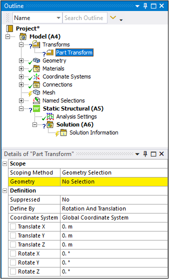
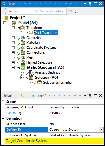
Select the Model object and then select the Part Transform option on Model context toolbar. As illustrated below, a Transforms folder object is placed in the Outline and automatically includes a Part Transform object. This folder object houses all of the part transformations.
Additional insertion options include:
Right-click on the Model object or in the Geometry window and select > Part Transform to insert these objects.
Select the parts/bodies you wish to transform from the Geometry object or on your model in the Geometry window, right-click, and then select .
As needed, change the settings of the Transforms object properties, including:
Transform Mesh: Options include Yes (default) and . This property controls whether the application automatically transforms the mesh of your transformed parts. Setting this property to instructs the application to clear the mesh of your transformed parts when updated.
Regenerate Contacts: Options include Yes and (default). This property controls whether the application automatically generates contact on your transformed parts.
Specify the Scoping Method property as either (default) or .
Specify your desired geometry:
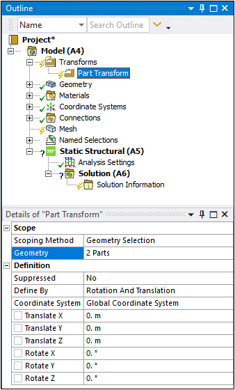
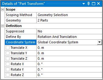
Select the entry field of the Geometry property and, using the Body selection filter on the Graphics toolbar, make geometry selections on the model, and then select the Apply button. Once specified, this field displays the number of parts you have selected (for example, 1 Part, 2 Parts, etc.). An example is illustrated below.
Or...
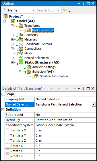
Select a body-based Named Selection from the Named Selection property drop-down list. Once specified, this field displays the specified Named Selection. An example is illustrated below.
Note: If you make a geometry selection using either the Face, Edge, or Vertex selection filters or if you specify a Named Selection based on any of these geometric entities, the application automatically selects the entire body associated with the entity. Mesh selection options are not supported.
Using the Define By property, select your transformation method. Options include (default) and .
Rotation and Translation: You use this option and the associated Transform X/Y/Z and Rotate X/Y/Z properties to specify the dimensions for moving or reorienting the selected parts. This option also provides an associated Coordinate System property that you can use to define a user-defined coordinate system instead of using the default Global Coordinate System setting. Note that the application applies the rotational transforms first, followed by translation transformations.
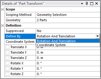
Coordinate System: You use this option and the associated (source) Coordinate System and Target Coordinate System properties to specify your transformation on the selected parts by coordinate systems. For this option, you need to manually create a Target Coordinate System that will be the basis of the transformation. The application reorients your selected parts by aligning the source coordinate system with the user-defined Target Coordinate System.
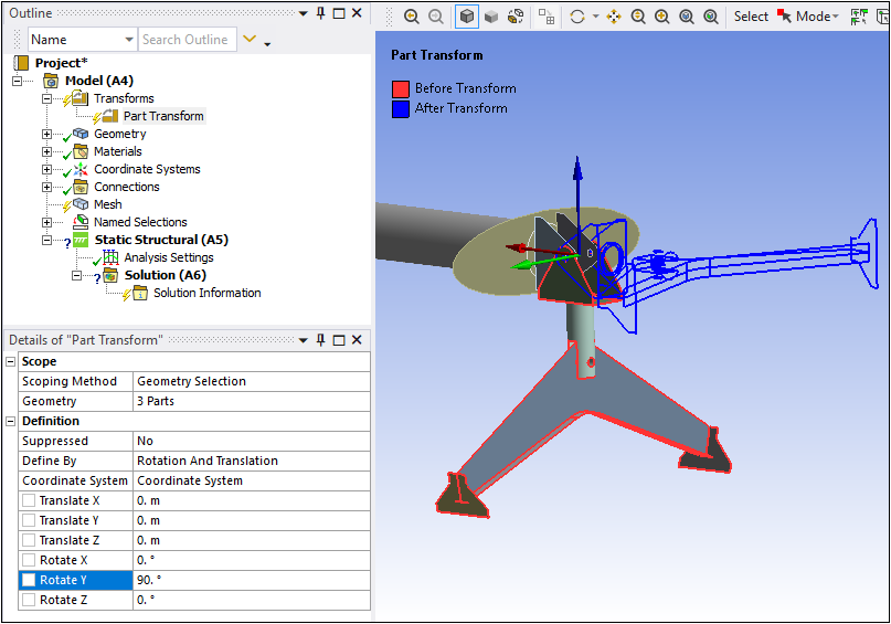
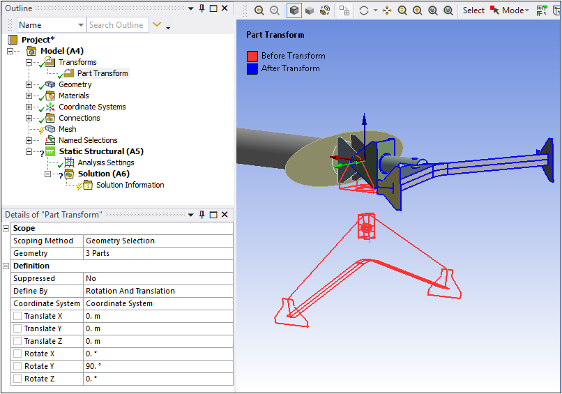
Specify your desired transformations. Once you complete your entries, the parts highlight as indicated by the annotations Before Transform/After Transform. The red display shows the current position of your parts and the blue highlight shows the pending location of the transformation. An example is illustrated below. A Coordinate System system is created for the transformation location and the parts are rotated 90° in the +Y direction.
Right-click on the Part Transform object (or the Transforms object) and select .
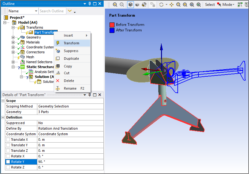
The parts are moved and/or reoriented as specified. Before and after highlights are also shown following the transformation.
You can perform additional transformations as needed. If you create multiple transformations, you can change their order in the Outline by dragging and dropping the objects onto one another.