


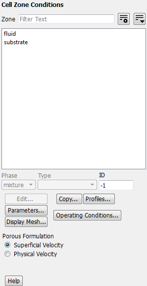
The Cell Zones Conditions task page allows you to set the type of a cell zone and display other dialog boxes to set the cell zone condition parameters for each zone. See Cell Zone Conditions for more information.
Controls
- Zone
contains a selectable list of available cell zones from which you can select the zone of interest. You can check a zone type by using the mouse probe (see Controlling the Mouse Button Functions) on the displayed physical mesh. This feature is particularly useful if you are setting up a problem for the first time, or if you have two or more cell zones of the same type and you want to determine the cell zone IDs. To do this you must first display the mesh with the Mesh Display Dialog Box. Then click the boundary zone with the right (select) mouse button. Ansys Fluent will print the cell zone ID and type of that boundary zone in the console window.
- Phase
specifies the phase for which conditions at the selected cell Zone are being set. This item appears if the VOF, mixture, or Eulerian multiphase model is being used. See Defining Multiphase Cell Zone and Boundary Conditions for details.
- Type
contains a drop-down list of condition types for the selected cell zone. The list contains all possible types to which the cell zone can be changed.
- ID
displays the cell zone ID number of the selected cell zone. (This is for informational purposes only; you cannot edit this number.)
- Edit...
opens the Fluid Dialog Box or Solid Dialog Box.
- Copy...
opens the Copy Conditions Dialog Box, which allows you to copy conditions from one cell zone to other cell zones of the same type. See Copying Cell Zone and Boundary Conditions for details.
- Profiles...
opens the Profiles Dialog Box.
- Parameters...
opens the Parameters Dialog Box.
- Operating Conditions...
opens the Operating Conditions Dialog Box.
- Display Mesh...
opens the Mesh Display Dialog Box.
- Porous Formulation
contains options for setting the velocity in the porous medium simulation. See Defining the Porous Velocity Formulation for details.
- Superficial Velocity
enables the superficial velocity in a porous medium simulation. This is the default method.
- Physical Velocity
enables the physical velocity in a porous medium simulation for a more accurate simulation. This option is available only for a pressure-based solver. See Modeling Porous Media Based on Physical Velocity for details.
For additional information, see the following sections:
- 51.6.1. Fluid Dialog Box
- 51.6.2. Solid Dialog Box
- 51.6.3. Copy Conditions Dialog Box
- 51.6.4. Operating Conditions Dialog Box
- 51.6.5. Select Input Parameter Dialog Box
- 51.6.6. Profiles Dialog Box
- 51.6.7. Replicate Profile Dialog Box
- 51.6.8. Orient Profile Dialog Box
- 51.6.9. Write Profile Dialog Box
- 51.6.10. Select Profiles for Writing
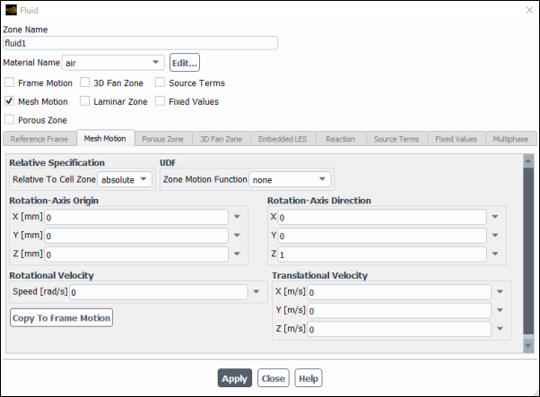
The Fluid dialog box sets the conditions for a fluid cell zone. It is opened from the Cell Zone Conditions Task Page. See Inputs for Fluid Zones and User Inputs for Porous Media for details about the items below.
Important: This feature offers reduced functionality when running Fluent under the Pro capability level.
Controls
- Zone Name
sets the name of the zone.
- Material Name
sets the fluid material. The drop-down list contains the names of all materials that have been loaded into the solver. Materials are defined with the Materials Task Page.
Important: If you are modeling species transport or multiphase flow, the Material Name list will not appear in the Fluid dialog box. For species calculations, the mixture material for all fluid zones will be the material you specified in the Species Model Dialog Box. For multiphase flows, the materials are specified when you define the phases, as described in Defining the Phases for the VOF Model.
- Phase
(multiphase models only) specifies the phase for which conditions at the selected fluid cell zone are being set.
- Frame Motion
enables the moving reference frame model for the cell zone. See Specifying the Rotation Axis and Defining Zone Motion for details.
- Mesh Motion
enables the sliding mesh model for the cell zone. See Setting Up the Sliding Mesh Problem for details.
- Porous Zone
indicates that the zone is a porous medium. Additional items will appear in the dialog box when this option is enabled. See User Inputs for Porous Media for details.
- 3D Fan Zone
allows you to simulate the effect of an axial fan by applying a distributed momentum source in a toroid-shaped fluid volume. This model can calculate not only the axial velocity, but the swirl and radial velocities as well. When you enable this option, the 3D Fan Zone tab becomes available, so that you can specify the geometry and properties of the fan. The cell zone should have a toroid shape that is sized to match the blade-swept volume of the fan you are simulating (that is, has an inner and outer radius that matches the radius of the fan’s hub and blade tips, respectively, as well as a length that matches the thickness of the toroid region swept by the blades in the axial direction). Furthermore, the fluid cell zone should be “interior”, that is, have at least two boundary zones of type interior that border another fluid cell zone and act as the fan inlet and outlet (the other boundaries can be of type interior as well). See 3D Fan Zones for details.
- Laminar Zone
disables the calculation of turbulence production in the fluid zone (appears only for turbulent flow calculations using the Spalart-Allmaras model or one of the
 -
-  or
or  -
-  models). See Specifying a Laminar Zone for details.
- LES Zone
allows you to model a smaller embedded LES zone within a larger URANS computational domain for turbulent flow calculations. When you turn on this option, the Embedded LES tab will be enabled to allow you to specify properties for the embedded LES zone. See Setting Up the Embedded Large Eddy Simulation (ELES) Model for details.
- Source Terms
enables the specification of volumetric sources of mass, momentum, energy, and so on. When you turn on this option, the Source Terms tab will be enabled to allow you to specify the values for the desired sources. See Defining Mass, Momentum, Energy, and Other Sources for details.
- Fixed Values
enables the fixing of the value of one or more variables in the fluid zone, rather than computing them during the calculation. See Fixing the Values of Variables for details.
Important: You can fix values for velocity components, temperature, and species mass fractions only if you are using the pressure-based solver.
- Participates In Radiation
specifies whether or not the fluid zone participates in radiation. This option appears when you are using the DO model for radiation.
Warning: In general, disabling Participates in Radiation for fluid zones is not recommended, as it can produce erroneous results. There are rare cases when it is acceptable: for example, if the domain contains multiple fluid zones, disabling this option for zones where radiation is negligible may save computational time without affecting the results.
- Reaction
enables/disables reactions in the porous zone.
- Electrolyte
indicates that the zone is an electrolyte zone. By default, all fluid zones are assumed to be electrolyte zones. This option appears when the Electrochemical Reaction model is enabled.
- Reference Frame Tab
lists the parameters that define motion for a moving reference frame.
- Rotation-Axis Origin
specifies the origin for the axis of rotation of the fluid zone. See Specifying the Rotation Axis for details. This item will appear only for 3D and 2D non-axisymmetric models.
- Rotation-Axis Direction
specifies the direction vector for the fluid zone’s axis of rotation. See Specifying the Rotation Axis for details. This item will appear only for 3D models.
- Rotational Velocity
contains an input field for the rotational Speed of the zone.
- Translational Velocity
contains inputs for the X, Y, and Z velocities of the zone.
- Relative Specification
indicates whether the velocities are absolute velocities (absolute) or velocities relative to the motion of each cell zone (Relative to Cell Zone). This selection is necessary only if your problem involves moving reference frames or sliding meshes. If there is no zone motion, both options are equivalent.
- UDF
allows you to hook the
DEFINE_ZONE_MOTIONuser-defined function.- Copy to Mesh Motion
allows you to switch between the MRF and moving mesh models. The variables used for the origin, axis, and velocity components, as well as for the
DEFINE_ZONE_MOTIONuser-defined function, will be copied from one model to the other.
- Mesh Motion Tab
lists the parameters that define motion for a moving reference frame.
- Rotation-Axis Origin
specifies the origin for the axis of rotation of the fluid zone. See Specifying the Rotation Axis for details. This item will appear only for 3D and 2D non-axisymmetric models.
- Rotation-Axis Direction
specifies the direction vector for the fluid zone’s axis of rotation. See Specifying the Rotation Axis for details. This item will appear only for 3D models.
- Rotational Velocity
contains an input field for the rotational Speed of the zone.
- Translational Velocity
contains inputs for the X, Y, and Z velocities of the zone.
- Relative Specification
indicates whether the velocities are absolute velocities (absolute) or velocities relative to the motion of each cell zone (Relative to Cell Zone). This selection is necessary only if your problem involves moving reference frames or sliding meshes. If there is no zone motion, both options are equivalent.
- UDF
allows you to hook the
DEFINE_ZONE_MOTIONuser-defined function.- Copy to Frame Motion
allows you to switch between the MRF and moving mesh models. The variables used for the origin, axis, and velocity components, as well as for the
DEFINE_ZONE_MOTIONuser-defined function, will be copied from one model to the other.
- Porous Zone Tab
lists the parameters associated with the porous zone.
- Conical
enables the specification of a conical (or cylindrical) porous medium. This item will appear only when the Porous Zone option is enabled for a 3D case.
- Cone Half Angle
specifies the angle between the cone’s axis and its surface (see Figure 7.23: Cone Half Angle). Set this to 0 to define the porous region using a cylindrical coordinate system. This item will appear only when the Porous Zone and Conical options are enabled.
- Snap to Zone
aligns the plane (or line, in 2D) tool with the zone selected in the drop-down list. The tool is centered at the centroid of the zone, with the tool’s axis normal to the zone. If this axis is not the desired cone axis, reposition the tool (as described in Using the Plane Tool). When you are satisfied with the axis, click the Update From Plane Tool (or Update From Line Tool) button to update the Cone Axis Vector fields.
This item will appear only when the Porous Zone and Conical options are enabled.
- Update From Plane Tool
(Update From Line Tool in 2D) updates the Direction-1 Vector and (in 3D) the Direction-2 Vector from the plane tool orientation. If the Conical option is enabled, this button will update the Cone Axis Vector and the Point on Cone Axis. See Defining the Viscous and Inertial Resistance Coefficients for details. This item will appear only when the Porous Zone option is enabled.
- Direction-1 Vector, Direction-2 Vector
indicate the directions for which the resistance coefficients are defined. See Defining the Viscous and Inertial Resistance Coefficients for details. These items will appear only when the Porous Zone option is enabled, but the Conical option is not. (In 2D, only Direction-1 Vector will appear.)
- Cone Axis Vector
specifies the X,Y,Z vector for the cone’s axis.
This item will appear only when the Porous Zone and Conical options are enabled.
- Point on Cone Axis
specifies a point on the cone’s axis. This point will be used by Ansys Fluent to transform the resistances to the Cartesian coordinate system.
This item will appear only when the Porous Zone and Conical options are enabled.
- Relative Velocity Resistance Formulation
allows Ansys Fluent to either apply the relative reference frame or the absolute reference frame. This allows for the correct prediction of the source terms.
- Viscous Resistance, Inertial Resistance
contain inputs for the viscous resistance coefficient
 and the inertial resistance coefficient
  in each direction.
See Defining the Viscous and Inertial Resistance Coefficients for details.
These items will appear only when the Porous Zone option is enabled.
in each direction.
See Defining the Viscous and Inertial Resistance Coefficients for details.
These items will appear only when the Porous Zone option is enabled.- Alternative Formulation
provides better stability to the calculation when your porous medium is anisotropic.
If you have enabled the Conical option, Direction-1 is the cone axis direction, Direction-2 is the normal to the cone surface (radial (
 ) direction for a cylinder), and Direction-3 is the circumferential (
 ) direction.
- Power Law Model
contains inputs for the C0 and C1 coefficients in the power law model for porous media. See Using the Power-Law Model for details.
- Relative Permeability
(Eulerian multiphase model only) is a group box where you can set relative permeability for the mixture. See Specifying the Relative Permeability for details.
- Capillary Pressure
(Eulerian multiphase model only) is a group box where you can set a model for capillary pressure for the mixture. See Capillary Pressure Usage for details.
- Relative Viscosity
is a group box where you can specify a model for relative viscosity. See Specifying the Relative Viscosity for details.
- Fluid Porosity
contains an additional input for the porous medium. See User Inputs for Porous Media for details.
- Porosity
sets the volume fraction of fluid within the porous region.
- Heat Transfer Settings
contains heat transfer settings for the porous medium. See Specifying the Heat Transfer Settings for details.
- Thermal Model
specifies whether or not thermal equilibrium is assumed between the medium and the fluid flow.
- Equilibrium
specifies that the medium and the fluid flow are in thermal equilibrium in the porous medium.
- Non-Equilibrium
specifies that the medium and the fluid flow are not in thermal equilibrium in the porous medium, so that a dual cell approach is enabled.
- Solid Material Name
specifies the solid material in the porous region. This drop-down menu is only available when Equilibrium is selected from the Thermal Model list.
- Solid Zone
displays the name of the solid cell zone that is coupled with the porous fluid zone through heat transfer. This field is only displayed when Non-Equilibrium is selected from the Thermal Model list.
- Interfacial Area Density
specifies
 (as described
in Non-Equilibrium Thermal Model Equations) for the porous region. This
text-entry box is only available when Non-Equilibrium is selected from the Thermal Model list.
(as described
in Non-Equilibrium Thermal Model Equations) for the porous region. This
text-entry box is only available when Non-Equilibrium is selected from the Thermal Model list.- Heat Transfer Coefficient
specifies
 (as described
in Non-Equilibrium Thermal Model Equations) for the porous region. This
text-entry box is only available when Non-Equilibrium is selected from the Thermal Model list.
(as described
in Non-Equilibrium Thermal Model Equations) for the porous region. This
text-entry box is only available when Non-Equilibrium is selected from the Thermal Model list.
- Anisotropic Species Diffusion
allows you to model anisotropic species diffusion in porous media. When this option is selected, you can specify the Matrix Components for the anisotropic diffusion matrix in the porous zone. This option is available only with the species transport models.
- 3D Fan Zone Tab
provides the settings that define a 3D fan zone. See 3D Fan Zones for details.
- Geometry
allows you to define the location and size of the fan.
- Inlet Fan Zone
allows you to select a boundary zone of type interior that will act as the surface on which the fan will be located.
- Hub Radius
defines the radius of the fan hub, that is, the inner radius of the blade-swept volume on which the fan’s distributed momentum sources are applied.
- Tip Radius
defines the radius of the blade tips of the fan, that is, the outer radius of the blade-swept volume on which the fan’s distributed momentum sources are applied.
- Thickness
defines the thickness of the toroid region swept by the blades in the axial direction.
- Inflection Point
is a ratio that defines the fraction of the fan blade length (starting at the hub) over which the tangential velocity of the fan discharge is increasing with increasing radius and peaks, before tapering off (see Figure 7.30: The Inflection Point Ratio of a Pitched Blade Turbine).
- Fan Origin
defines the X, Y, and Z coordinates of a point on the Inlet Fan Zone that is the origin for the fan.
- Properties
allows you to define how the fan behaves.
- Rotational Direction
allows you to define the fan’s rotational direction, using the right-hand rule with respect to the fan direction vector (that is, a vector from the Fan Origin that points into the 3D fan zone perpendicular to the Inlet Fan Zone).
- Operating Angular Velocity
defines the angular velocity of the fan during the simulation.
- Limit Flow Rate Through Fan
specifies that the flow rate through the fan adheres to minimum and maximum values, as defined in the Flow Rate group box.
- Flow Rate
allows you to define the Maximum and Minimum flow rates through the fan. This group box is available when the Limit Flow Rate Through Fan option is enabled.
- Tangential Source Term
enables a momentum source in the tangential direction, based on impeller theory.
- Radial Source Term
enables a momentum source in the radial direction, based on impeller theory.
- Axial Source Term
enables a momentum source in the axial direction, based on the settings in the Axial Source Term Settings group box.
- Axial Source Term Settings
allows you to define the momentum source in the axial direction. This group box is only available when the Axial Source Term option is enabled.
- Method
specifies whether a constant pressure or a fan curve (that is, a curve created from data points that plot pressure rise vs. volumetric flow rate) defines the axial momentum source.
- Pressure Jump
defines the pressure jump that is applied across the 3D fan. This setting is only available when constant pressure is selected for the Method.
- Read Fan Curve...
allows you to read a tab-delimited ASCII file that defines the relationship between pressure and flow rate for each 3D fan cell zone (see 3D Fan Curve File Format for details). This button is only available when fan curve is selected for the Method.
- Curve Fitting Method
specifies whether Fluent should apply a polynomial or piecewise-linear fitting method to construct a curve from the data points in the fan curve file. This drop-down list is only available when fan curve is selected for the Method.
- Order of Polynomial
defines the order of the polynomial curve fitting method. This setting is only available when polynomial is selected for the Curve Fitting Method.
- Initial Flow Rate
specifies your best estimate of the initial flow rate through the fan. This setting is only available when fan curve is selected for the Method.
- Test Angular Velocity
specifies the angular velocity of the fan used in the experiment that generated the fan curve data. This setting is only available when fan curve is selected for the Method.
- Test Temperature
specifies the temperature of the fluid flowing through the fan during the experiment that generated the fan curve data. This setting is only available when fan curve is selected for the Method.
- Reaction Tab
lists the parameters for reactions in the porous zone.
- Reaction Mechanism
allows you to specify a defined group, or mechanism, of available reactions. See Defining Zone-Based Reaction Mechanisms for details about defining reaction mechanisms.
- Surface-to-Volume Ratio
specifies the surface area of the pore walls per unit volume (
 ), and can be thought of as a measure of catalyst
loading. With this value, Ansys Fluent can calculate the total surface
area on which the reaction takes place in each cell by multiplying
), and can be thought of as a measure of catalyst
loading. With this value, Ansys Fluent can calculate the total surface
area on which the reaction takes place in each cell by multiplying  by the volume of the
cell.
by the volume of the
cell.
- Source Terms Tab
defines a source of heat, mass, momentum, turbulence, species, or other scalar quantity within the fluid zone.
- Fixed Values Tab
allows you to specify which variables in the fluid zone are fixed (as a constant value or as defined by a profile or user-defined function), rather than computed during the calculation. See Fixing the Values of Variables for details.
- Local Coordinate System for Fixed Velocities
enables the specification of fixed cylindrical velocity components instead of Cartesian components. The local coordinate system is defined by the Rotation-Axis Origin and Rotation-Axis Direction.
This item is available only in 3D, and only when the Fixed Values option is on.
- Multiphase Tab
allows you to set parameters that are specific to the multiphase models.
- Compressive Scheme Slope Limiter
ranges from 0 to 2. For example, a Compressive Scheme Slope Limiter of 0 corresponds to first order upwind behavior, a value of 1 corresponds to second order upwind, and a value of 2 applies the compressive scheme. The Multiphase tab is available only if Zonal Discretization is enabled in the Multiphase Model Dialog Box.
- Numeric Beach Treatment
is available when Open Channel Flow and/or Open Channel Wave BC is enabled in the Multiphase Model dialog box (see Numerical Beach Treatment for Open Channels for more detail).
- Numerical Beach
when enabled expands the dialog box where you can specify the numerical beach parameters.
- Beach Group ID
represents the cell zones sharing the damping length containing the same input parameters.
- Damping Type
allows you to choose between One Dimensional and Two Dimensional damping.
- One Dimensional
is the damping treatment in the flow direction.
- Two Dimensional
is the damping treatment in the flow and gravity direction.
- Compute From Inlet Boundary
is set to none by default. If there are available open channel boundaries (velocity-inlet, pressure-inlet, and mass-flow-inlet), boundary names are added to the drop-down list. If you select a boundary from the list, the Level Inputs, Damping Length Inputs in Flow Direction, and Damping Resistance values will be updated in the interface. You have the option to overwrite the updated inputs with values that are more applicable to your simulation.
- Level Inputs
is only available for the Two Dimensional damping type.
- Free Surface Level
is the same definition as for open channel flow, see Modeling Open Channel Flows.
- Bottom Level
is the same definition as for open channel flow, see Modeling Open Channel Flows, and is valid only for shallow waves. The bottom level is used for calculating the liquid height.
- Flow Direction
is the X, Y, and Z (for 3D) components.
- Damping Length Inputs in Flow Direction
are required to calculate the start and end points of the damping length in the flow direction.
- Damping Length Specification
is only available if Open Channel Wave BC is enabled in the Multiphase Model dialog box. There are two options you can choose from End Point and Wave Lengths or End and Start Points.
- End Point
is the end point of the damping zone.
- Start Point
is the starting point in the flow direction.
- Wave Length
is updated automatically if the boundary is selected from the Compute From Inlet Boundary drop-down list.
- Number Of Wave Lengths
is set to 2 by default for the calculation of the damping length.
- Relative Velocity Resistance Formulation
calculates the source term using relative velocities in the numerical beach zone when using moving/deforming meshes or moving reference frames.
- Linear Damping Resistance
is the resistance per unit time.
- Quadratic Damping Resistance
is the resistance per unit length.
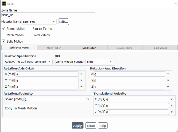
The Solid dialog box sets the boundary conditions for a solid cell zone. It is opened from the Cell Zone Conditions Task Page. See Inputs for Solid Zones for details about the items below.
Controls
- Zone Name
sets the name of the zone.
- Material Name
selects the material type of the solid. Materials are defined with the Materials Task Page.
- Frame Motion
enables the moving reference frame model for the cell zone. This option is suitable when the solid zone is moving, but the motion is not relative to an adjacent solid zone. See Defining Zone Motion and Modeling Flows with Moving Reference Frames for details.
- Mesh Motion
enables the sliding mesh model for the cell zone. See Defining Zone Motion and Setting Up the Sliding Mesh Problem for details.
- Solid Motion
enables the solid motion model for the cell zone. This option is suitable when the solid zone is moving relative to an adjacent solid zone. See Defining Zone Motion for details.
- Source Terms
enables the specification of a volumetric source of energy. When you turn on this option, the Source Term tab will allow you to specify the value for the energy source. See Defining Mass, Momentum, Energy, and Other Sources for details.
- Fixed Values
enables the fixing of the value of one or more variables in the solid zone, rather than computing them during the calculation. See Fixing the Values of Variables for details.
Important: You can fix the value of temperature only if you are using the pressure-based solver.
- Participates In Radiation
specifies whether or not the solid zone participates in radiation. This option appears when you are using the DO model for radiation.
- Reference Frame Tab
lists the parameters that define motion for a moving reference frame. For further details about the following, see Defining Zone Motion.
- Relative Specification
provides the Relative To Cell Zone drop-down list, which allows you to indicate whether the velocities are absolute velocities (absolute) or are relative to the motion of a selected cell zone.
- UDF
provides the Zone Motion Function drop-down list, which allows you to hook a
DEFINE_ZONE_MOTIONuser-defined function that defines the zone motion.- Rotation-Axis Origin
specifies the origin for the axis of rotation of the solid zone. This item will appear only for 3D and 2D non-axisymmetric models.
- Rotation-Axis Direction
specifies the direction vector for the solid zone's axis of rotation. This item will appear only for 3D models.
- Rotational Velocity
contains an input field for the rotational Speed of the zone.
- Translational Velocity
contains inputs for the X, Y, and Z velocities of the zone.
- Copy to Mesh Motion
allows you to switch from frame motion to mesh motion. The variables used for the origin, axis, and velocity components, as well as for the
DEFINE_ZONE_MOTIONuser-defined function, will be copied from one model to the other.
- Mesh Motion Tab
lists the parameters that define motion for a moving reference frame. For further details about the following, see Defining Zone Motion.
- Relative Specification
provides the Relative To Cell Zone drop-down list, which allows you to indicate whether the velocities are absolute velocities (absolute) or are relative to the motion of a selected cell zone.
- UDF
provides the Zone Motion Function drop-down list, which allows you to hook a
DEFINE_ZONE_MOTIONuser-defined function that defines the zone motion.- Rotation-Axis Origin
specifies the origin for the axis of rotation of the solid zone. This item will appear only for 3D and 2D non-axisymmetric models.
- Rotation-Axis Direction
specifies the direction vector for the solid zone's axis of rotation. This item will appear only for 3D models.
- Rotational Velocity
contains an input field for the rotational Speed of the zone.
- Translational Velocity
contains inputs for the X, Y, and Z velocities of the zone.
- Copy to Frame Motion
allows you to switch from mesh motion to frame motion. The variables used for the origin, axis, and velocity components, as well as for the
DEFINE_ZONE_MOTIONuser-defined function, will be copied from one model to the other.
- Solid Motion Tab
lists the parameters that define solid motion, when the solid zone is moving relative to an adjacent solid zone. For further details about the following, see Defining Zone Motion.
- Relative Specification
provides the Relative To Cell Zone drop-down list, which allows you to indicate whether the velocities are absolute velocities (absolute) or are relative to the motion of a selected cell zone.
- UDF
provides the Solid Motion Function drop-down list, which allows you to hook a
DEFINE_ZONE_MOTIONuser-defined function that defines the zone motion.- Rotation-Axis Origin
specifies the origin for the axis of rotation of the solid zone. This item will appear only for 3D and 2D non-axisymmetric models.
- Rotation-Axis Direction
specifies the direction vector for the solid zone's axis of rotation. This item will appear only for 3D models.
- Rotational Velocity
contains an input field for the rotational Speed of the zone.
- Translational Velocity
contains inputs for the X, Y, and Z velocities of the zone.
- Copy to Mesh Motion
allows you to switch from solid motion to mesh motion. The variables used for the origin, axis, and velocity components, as well as for the
DEFINE_ZONE_MOTIONuser-defined function, will be copied from one model to the other.
- Source Term Tab
lists the parameters for volumetric source of energy.
- Energy
displays the total number of energy sources used.
- User Scalar n
displays the total number of scalars used.
- Fixed Values Tab
allows you to specify which variables in the solid zone are fixed (as a constant value or as defined by a profile or user-defined function), rather than computed during the calculation. See Fixing the Values of Variables for details.
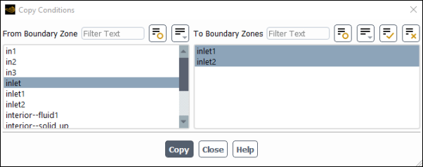
The Copy Conditions dialog box allows you to copy cell zone and/or boundary conditions from one zone/boundary to other zones/boundaries of the same type. It is opened either from the Cell Zone Conditions Task Page or from the Boundary Conditions Task Page. See Copying Cell Zone and Boundary Conditions for details.
Controls
- From Zone
specifies the zone that has the conditions you want to copy.
- To Zones
specifies the zone or zones to which you want to copy the conditions.
- Phase
specifies the phase for which cell zone conditions or boundary conditions are being copied. This item appears if the VOF, mixture, or Eulerian multiphase model is being used. See Steps for Copying Cell Zone and Boundary Conditions for details.
- Copy
copies the cell zone conditions or boundary conditions, setting all of the conditions for the zones selected in the To Zones list to be the same as the conditions for the zone selected in the From Zone list.
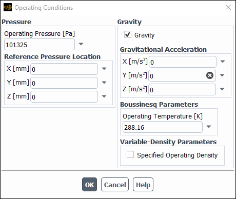
The Operating Conditions dialog box allows you to set parameters related to operating conditions in your model.
Controls
- Pressure
contains items related to the modeling of pressure.
- Floating Operating Pressure
specifies the use of a floating operating pressure. See Floating Operating Pressure for details. This option appears only for time-dependent compressible flows that use the ideal or real gas model.
- Operating Pressure
sets the operating pressure for the problem. For all flows, Ansys Fluent uses gauge pressure internally. Any time an absolute pressure is needed, it is generated by adding the operating pressure to the relative pressure. See Operating Pressure for a detailed description of operating pressure and how to set it.
- Reference Pressure Location
sets the location of the cell whose pressure value is used to adjust the gauge pressure field for incompressible flows that do not involve any pressure boundaries. See Using a Reference Pressure to Adjust the Gauge Pressure Field for details.
Note: The pressure at the reference pressure location is used to correct the gauge pressure. This is not related to the reference pressure quantity in postprocessing.
- Real Gas State
allows you to specify the operating conditions in the subcritical regime of your model. Note that if the operating conditions in your model are entirely in the supercritical regime, this setting will have no effect.
Note: This option appears only when a Cubic Equation of State Real Gas model is chosen.
- Vapor
is the default option, and therefore assumes that the real gas state is vapor.
- Liquid
assumes that the real gas state is liquid.
- Gravity
contains inputs for gravitational acceleration, the Boussinesq model, and variable density.
- Gravity
enables the specification of gravity.
- Gravitational Acceleration
sets the
 ,
,  , and
, and  components of the gravitational acceleration vector.
(The
components of the gravitational acceleration vector.
(The  component is available only in 3D solvers.) See Buoyancy-Driven Flows and Natural Convection for details about buoyancy-driven
flows. This option appears only when Gravity is
enabled.
component is available only in 3D solvers.) See Buoyancy-Driven Flows and Natural Convection for details about buoyancy-driven
flows. This option appears only when Gravity is
enabled.- Boussinesq Parameters
contains inputs related to the Boussinesq model. This option appears only if Energy (in the Energy Dialog Box) and Gravity are enabled. See The Boussinesq Model for more information on the Boussinesq model.
- Operating Temperature
sets the operating temperature (
 in Equation 7–67) for use with the Boussinesq approximation.
- Variable-Density Parameters
contains inputs related to the modeling of variable density. This option appears only when Gravity is enabled.
- Specified Operating Density
enables the specification of operating density. See If you are using the incompressible ideal gas law, check the Operating Density for details. This item is available for single-phase flows only.
- Operating Density Method
specifies which method will be used to calculate the operating density. You can choose minimum-phase-averaged, primary-phase-averaged, mixture-averaged, or user-input. For information about these methods, see Modeling Buoyancy-Driven Multiphase Flow.This item is available for buoyancy-driven multiphase flows only.
- Operating Density
sets the operating density (
 in Equation 7–68). This item is available when
either Specified Operating Density is enabled for a single-phase
flow or the user-input operating density method is selected for a
multiphase flow.
in Equation 7–68). This item is available when
either Specified Operating Density is enabled for a single-phase
flow or the user-input operating density method is selected for a
multiphase flow.
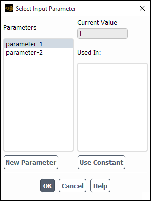
The Select Input Parameter dialog box allows you to choose from a listing of existing input parameters as well as to create and define new input parameters. For more information about parameters, see Defining and Viewing Parameters in the User's Guide, and see Working With Input and Output Parameters in Workbench in the Ansys Fluent in Workbench User's Guide.
Controls
- Parameters
contains a list of existing compatible input parameters
- Current Value
displays the value of the currently selected parameter.
- Used In
lists any variables that are already associated with the currently selected parameter.
- Use Constant
allows you to change the associated parameter to a constant (that is, real) value.
- New Parameter
opens the Parameter Expression Dialog Box, in which you can assign names and values to an input parameter.
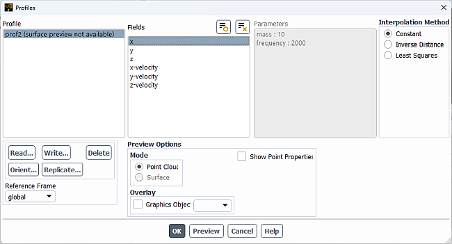
The Profiles dialog box allows you to define new profiles by reading cell zone and boundary profile files. You can also examine the existing profile definitions and delete unused profiles. See Profiles for details about cell zone and boundary profiles.
Controls
- Profile
contains a selectable list of available profiles. When a profile is selected its available fields are displayed under Fields. Parameters, if included in the profile, are displayed under Parameters.
- Fields
displays the fields available in the selected profile. After the profile file has been read, these fields will also appear in any boundary condition dialog box (for example, the Velocity Inlet dialog box) that allows profile specification of a variable. To the right of (or below) the variable in the boundary conditions dialog box, there will be a drop-down list that contains a constant and the fields from available profile files. To use a particular profile field, just select it from the list.
- Parameters
contains a read-only list of parameters included in the selected CSV profile (when applicable).
- Interpolation Method
allows you to select the interpolation method for the profile selected from the Profile list. This selection is only available for point profiles, and will only take effect when the Apply button is clicked. The choices include the following:
- Constant
specifies that Ansys Fluent should use zeroth-order interpolation to assign the point profile values to the nearest cell faces at the boundary. This is the default selection.
- Inverse Distance
specifies that Ansys Fluent should assign a value to each cell face at the boundary based on weighted contributions from the values in the point profile file. The weighting factor is inversely proportional to the distance between the profile point and the cell face center.
- Least Squares
specifies that Ansys Fluent should assign values to the cell faces at the boundary through a first-order interpolation method that tries to minimizes the sum of the squares of the offsets (residuals) between the profile data points and the cell face centers.
- Reference Frame
allows you to attach the profile to a reference frame. If you select a reference frame other than global, then the profile will follow the orientation and/or motion of the specified reference frame.
- Read...
opens The Select File Dialog Box so that you can read a boundary profile file. If a profile in the file has the same name as an existing profile, the old profile will be overwritten.
- Write...
opens the Write Profile Dialog Box, in which you can save profile data.
- Delete
deletes the selected profile from memory.
- Orient...
opens the Orient Profile Dialog Box, in which you can reorient and scale the profile. This item appears only in 3D.
- Replicate...
opens the Replicate Profile Dialog Box, in which you can reorient and scale the profile. This item appears only in 3D.
- Preview Options
contains options for previewing profiles as a cloud of points or as a surface.
- Point Cloud
preview the profile as a cloud of points.
- Surface
preview the profile as a surface. This option requires that the profile contain node-connectivity data. Profile that do not have this data are indicated as such in the Profile list.
- Show Point Properties
optionally expands additional settings for how points are displayed when previewing the profile as a point cloud.
- Symbol
specifies the symbol used to represent the points in the point cloud preview.
- Size
controls the size of the points in the point cloud preview.
- Color
specifies the color of the points in the point cloud preview.
- Overlay Graphics Object
allows you to overlay any defined mesh or contour plots when previewing a profile as either a surface or a point cloud.
sets the selection made in the Interpolation Method list for point profiles in preparation for interpolation. The profile is not actually interpolated until a profile field is selected in a boundary condition dialog box (for example, the Velocity Inlet dialog box) and the solution is initialized.
displays the selected profile as either a point cloud or a surface, depending on which Mode is selected.
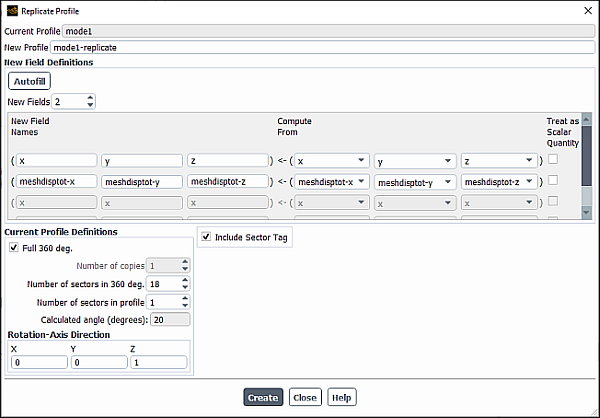
The Replicate Profile dialog box allows you to replicate a profile periodically, typically for use as a boundary condition in a turbomachinery case. See Replicating Profiles for details.
Controls
- Current profile
shows the name of the currently selected profile in the Profiles Dialog Box. This is the profile on which the new profile will be based.
- New Profile
sets the name of the new cell zone or boundary profile.
- New Field Definitions
contains inputs and controls for the definition of the vector and scalar fields in the new profile.
- New Fields
sets the number of data fields in the new profile.
- New Field Names
contains inputs for the names of the data fields in the new profile. For a vector field, all 3 inputs in each row will be active; for a scalar field, only the first will be active.
- Compute From...
contains drop-down lists with the names of the fields in the Current profile. In these lists, select the fields from which the New Field Names will be computed.
- Treat as Scalar Quantity
indicates (if on) that the adjacent field is a scalar quantity. If this option is off, the field is a vector quantity.
- Current Profile Definitions
contains inputs for the replication of the new profile.
- Full 360 deg.
automatically determines the number of copies of the original profile that are needed to make the full 360 degree profile based on the other information you specify
- Number of copies
specifies how many copies of the original profile are created.
- Number of sectors in 360 deg.
the number of periodic sections, based on the original profile, that are present in 360 degrees.
- Number of sectors in profile
the number of periodic sections in the original profile.
- Calculated angle
(for display only) the angle occupied by the original profile.
- Create
creates a new profile using the information specified in the dialog box.
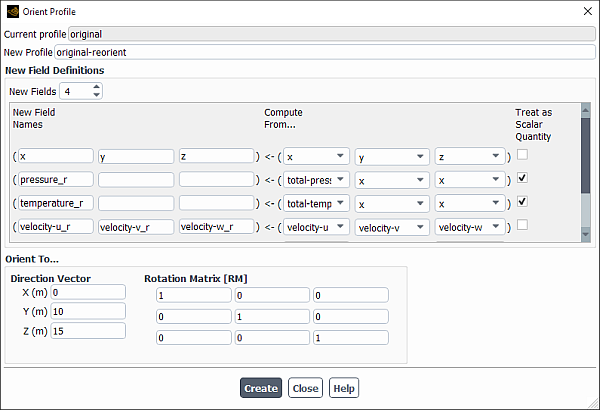
The Orient Profile dialog box allows you to reorient a profile so that you can apply it to a particular boundary. See Reorienting Profiles for details.
Controls
- Current profile
shows the name of the currently selected profile in the Profiles Dialog Box. This is the profile on which the new profile will be based.
- New Profile
sets the name of the new cell zone or boundary profile.
- New Field Definitions
contains inputs and controls for the definition of the vector and scalar fields in the new profile.
- New Fields
sets the number of data fields in the new profile.
- New Field Names
contains inputs for the names of the data fields in the new profile. For a vector field, all 3 inputs in each row will be active; for a scalar field, only the first will be active.
- Compute From...
contains drop-down lists with the names of the fields in the Current profile. In these lists, select the fields from which the New Field Names will be computed.
- Treat as Scalar Quantity
indicates (if on) that the adjacent field is a scalar quantity. If this option is off, the field is a vector quantity.
- Orient To...
contains inputs for the definition of the local coordinate system for the new profile. This coordinate system will determine the orientation of the profile.
- Direction Vector
is the vector that translates a cell zone or boundary profile to the new position, and is defined between the centers of the profile fields.
- Rotation Matrix [RM
] specifies the rotational matrix
 , which is based
on Euler angles (
, which is based
on Euler angles ( ,
,  , and
, and  ) that define an orthogonal system
  as the result of the three successive rotations
from the original system
as the result of the three successive rotations
from the original system  . See Reorienting Profiles for more information.
- Create
creates a new profile using the information specified in the dialog box.
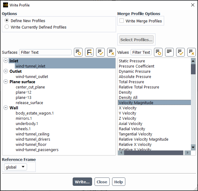
The Write Profile dialog box allows you to create a profile file from the conditions on a specified cell zone or boundary/surface. See Writing Profile Files for details on writing profile files.
Controls
- Options
contains options for writing profiles.
- Define New Profiles
enables the creation of a profile file from the conditions on a specified boundary or surface.
- Write Currently Defined Profiles
enables the creation of a profile file containing all profiles that are currently defined.
- Merge Profile Options
- Write Merge Profiles
(only available if two or more surfaces are selected) writes a .csv file with the selected surfaces consolidated into one set of data points.
- Select Profile...
opens the Select Profiles for Writing, allowing you to specify which profiles are written.
- Surfaces
contains a selectable list of surfaces where data can be extracted to write a profile.
- Values
contains a selectable list of variables that you use for creating profiles.
- Reference Frame
selectable list of reference frames that specifies which reference frame will be used in writing the profile.
- Write...
opens The Select File Dialog Box, where you can specify a filename for the profile file.
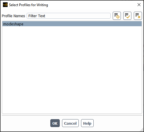
The Select Profiles for Writing dialog box allows you to select which of the profiles associated with the current case are written when you click in the Write Profile Dialog Box See Writing Profile Files for details on writing profile files.
Controls
- Profile Names
selectable list of profiles associated with the currently-loaded case that allows you to chose which profile(s) is written when you click in the Write Profile Dialog Box.