


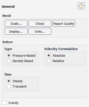
The General task page allows you to set various generic problem settings, such as those related to the mesh or the solver. Note that these settings become available only after you read in a case or mesh file. See Reading Mesh Files and Reading and Writing Case Files for details.
Important: This feature offers reduced functionality when running Fluent under the Pro capability level.
Controls
- Mesh
contains controls relating to mesh settings.
- Scale...
opens the Scale Mesh Dialog Box.
- Check
verifies the validity of the mesh. The check provides volume statistics, mesh topology and periodic boundary information, verification of simplex counters, and verification of node position with reference to the
 axis for axisymmetric cases.
See Checking the Mesh for details.
axis for axisymmetric cases.
See Checking the Mesh for details.It is recommended that you check the mesh right after reading it into the solver, in order to detect any mesh trouble before you get started with the problem setup.
- Report Quality
displays various quantities related to the quality of the mesh in the console, such as
Minimum Orthogonal QualityandMaximum Aspect Ratio. See Mesh Quality for details.- Display...
opens the Mesh Display Dialog Box.
- Solver
contains controls relating to solver settings.
- Type
contains the solution methods available for computing a solution for your model. See Using the Solver for details.
- Pressure-Based
enables the pressure-based Navier-Stokes solution algorithm (the default).
- Density-Based
enables the density-based Navier-Stokes coupled solution algorithm.
- Velocity Formulation
specifies the velocity formulation to be used in the calculation. See Choosing the Relative or Absolute Velocity Formulation for details.
- Absolute
enables the use of the absolute velocity formulation. This is the default setting.
- Relative
enables the use of the relative velocity formulation. This option is available only with the Pressure-Based solver.
- Time
contains options related to time dependence.
- Steady
specifies that a steady flow is being solved.
- Transient
enables a time-dependent solution. See Performing Time-Dependent Calculations for details.
- 2D Space
contains options available only when solving two-dimensional problems.
- Planar
indicates that the problem is two-dimensional. (This option is available only when you start the
2Dversion of the solver.)- Axisymmetric
indicates that the domain is axisymmetric about the
 axis. When Axisymmetric is enabled, the 2D axisymmetric form of the governing equations
is solved instead of the 2D Cartesian form. (This option is available
only when you start the
axis. When Axisymmetric is enabled, the 2D axisymmetric form of the governing equations
is solved instead of the 2D Cartesian form. (This option is available
only when you start the 2Dversion of the solver.) Be sure to change the zone type of the axis of rotation to axis, using the Boundary Conditions Task Page, as described in Changing Cell and Boundary Zone Types.- Axisymmetric Swirl
specifies that the swirl component (circumferential component) of velocity is to be included in your axisymmetric model. You should select this option if you are solving swirling flow in an axisymmetric geometry (see Swirling and Rotating Flows for more information).
- Gravity
enables the specification of gravity.
- Gravitational Acceleration
sets the
 ,
,  , and
, and  components of the gravitational acceleration vector.
(The
components of the gravitational acceleration vector.
(The  component is available only in 3D solvers.) See Buoyancy-Driven Flows and Natural Convection for details about buoyancy-driven
flows. This option appears only when Gravity is
enabled.
component is available only in 3D solvers.) See Buoyancy-Driven Flows and Natural Convection for details about buoyancy-driven
flows. This option appears only when Gravity is
enabled.- Units...
opens the Set Units Dialog Box.
For additional information, see the following sections:
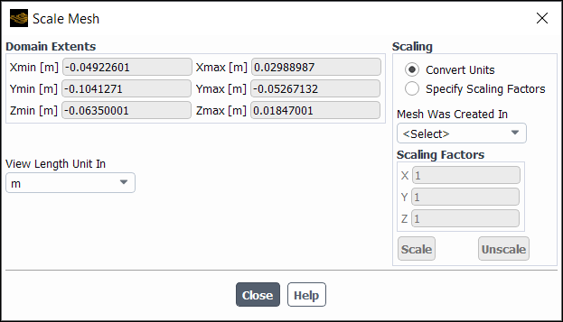
The Scale Mesh dialog box allows you to convert the mesh from various units of measurement to SI or to apply custom scale factors to the individual coordinates of the mesh. See Scaling the Mesh for details.
Controls
- Domain Extents
displays the Cartesian coordinate extremes of the nodes in the mesh. (These values are not editable; they are purely informational.)
- Xmin, Ymin, Zmin
shows the minimum values of Cartesian coordinates in the mesh.
- Xmax, Ymax, Zmax
shows the maximum values of Cartesian coordinates in the mesh.
- Scaling
contains controls for converting units and setting the scale factors automatically.
- Convert Units
allows you to use the conversion factors provided by Ansys Fluent. Then indicate the units used when creating the mesh by selecting the appropriate abbreviation for meters, centimeters, millimeters, inches, or feet from the Mesh Was Created In drop-down list. The Scaling Factors will automatically be set to the correct values (for example, 0.0254 meters/inch).
- Specify Scaling Factors
allows you to manually specify a scale factor in each of the Cartesian coordinate directions.
- Mesh Was Created In
contains a list of common units of length. The Scaling Factors will automatically be set based on your selection. The units include common SI and British units such as centimeters (cm), millimeters (mm), inches (in), and feet (ft).
- Scaling Factors
contains the factors applied to the mesh in each of the Cartesian coordinate directions. You can enter values manually, or use the Mesh Was Created In list to set scale factors automatically.
- X
is the scale factor in the
 direction.
- Y
is the scale factor in the
 direction.
- Z
is the scale factor in the
 direction (appears only in 3D).
- Scale
multiplies each of the node coordinates by the specified scale factors.
- Unscale
divides each of the node coordinates by the specified scale factors.
- View Length Unit In
contains a list of common units of length. The Domain Extents will automatically be set based on your selection. The units include common SI and British units such as centimeters (cm), millimeters (mm), inches (in), and feet (ft). The units of length in the Set Units Dialog Box will change each time you change your selection in the View Length Unit In drop-down list.
The Mesh Display dialog box controls the display of zone, surface, and partition boundary meshes. See Displaying the Mesh for details about the items below.
You can also access the Mesh Display dialog box through the Results ribbon tab.
![]() Results → Graphics
→ Mesh → New...
Results → Graphics
→ Mesh → New...
Note: If you click the mesh display toolbar button (![]() ), it opens the "global"/non-persistent version of the Mesh
Display dialog box. This version of the dialog box does not have a
Name field and it is not saved with the case file.
), it opens the "global"/non-persistent version of the Mesh
Display dialog box. This version of the dialog box does not have a
Name field and it is not saved with the case file.
You are encouraged to use the persistent version that is accessed by clicking New... in the Results ribbon tab if you anticipate wanting to display the same areas of the mesh in a future Fluent session or if you want to reuse the mesh display for other purposes, such as displaying a scene (Generating a Scene).
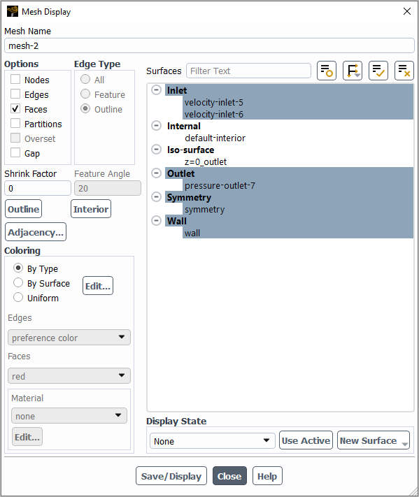
Controls
- Mesh Name
is the name for a mesh display definition. You can specify a name or use the default name
mesh-. This control appears only for mesh display definitions.id- Options
contains the rendering options described below. To see the effects of your selection you must click the Display button.
- Nodes
enables the display of nodes on the selected surfaces.
- Edges
enables the display of mesh edges on the selected surfaces.
- Faces
enables the display of mesh faces (filled meshes) on the selected surfaces.
- Partitions
enables the display of partition boundaries.
- Overset
when enabled, displays only the solve cells for cases with overset interfaces. Receptor cells are also displayed if the text command
define/overset-interfaces/options/render-receptor-cells?is set toyes.- Gap
enables the display of only the cells in which flow is allowed by the gap model (that is, those that are not marked for blockage in the gap region). This option is only available when you have created a gap definition, which can be done by using the Gap Model dialog box. For details about the gap model, see Controlling Flow in Narrow Gaps for Valves and Pumps.
- Shrink Factor
specifies the amount to shrink faces and cells. See Shrinking Faces and Cells in the Display for details.
- Edge Type
controls the display of edges. (These items will not appear if the Edges option is turned off.)
- All
enables the display of all mesh edges.
- Feature
enables feature lines in an outline display. See Adding Features to an Outline Display for details.
- Outline
enables the display of the mesh outline.
- Feature Angle
controls the amount of detail added to a feature outline display. See Adding Features to an Outline Display for details. (This item will be available only if the Feature edge type is enabled.)
- Transparency
(global mesh display only, accessed by clicking the mesh display toolbar button
 ) controls the transparency of the mesh display.
- Surfaces
contains a list from which you can select the surfaces for which the mesh is to be drawn.
- New Surface
is a drop-down list button that contains a list of surface options:
- Point
opens the Point Surface Dialog Box.
- Line/Rake
opens the Line/Rake Surface Dialog Box.
- Plane
opens the Plane Surface Dialog Box.
- Quadric
opens the Quadric Surface Dialog Box.
- Iso-Surface
opens the Iso-Surface Dialog Box.
- Iso-Clip
opens the Iso-Clip Dialog Box.
- Structural Point
opens the Structural Point Surface Dialog Box.
- Outline
selects all "outline" boundaries in the Surfaces list. If all outline boundaries are already selected, it deselects them.
- Interior
selects all "interior" surfaces in the Surfaces list. If all interior surfaces are already selected, it deselects them.
- Adjacency
opens the Adjacency Dialog Box from which you can identify and display face zones that are adjacent to selected cell zones.
- Coloring
- By Type
nodes, edges, and faces are automatically colored by type. The colors for each type are determined in the Zone Type Color and Material Assignment Dialog Box.
opens Zone Type Color and Material Assignment Dialog Box if By Type is selected or Surface Rendering Properties Dialog Box if By Surface is selected.
- By Surface
nodes, edges, and faces are colored by zone ID by default. However, you can assign colors and/or materials to surfaces so they are rendered consistently anytime the By Surface option is selected within a Mesh Display graphics object. Click Edit... when By Surface is selected to open the Surface Rendering Properties Dialog Box and make these assignments.
Note that if you do not like the default colors assigned with this method, you can use Ctrl+Shift+O to randomize the mesh colors. Ensure the graphics window is in focus by clicking in it before using the hotkey combination (otherwise it won't work).
- Uniform
allows you to manually specify the color of edges, and faces, if enabled under Options.
- Edges
specify the color for the edges.
- Faces
specify the color for the faces.
- Material
specify the material type for the selected surfaces.
opens the Material Editor Dialog Box. Refer to Creating Custom Realistic Materials for additional information on using the Material Editor dialog box.
- Colors...
(available only for the "global"/non-persistent dialog box access by clicking the mesh display icon
) opens the Mesh Colors Dialog Box.- Display
(available only for the "global"/non-persistent dialog box access by clicking the mesh display icon
) displays the defined mesh plot.- Save/Display
displays the mesh in the active graphics window and saves the mesh display definition. This button appears only for mesh display definitions and replaces the Display button.
The Set Units dialog box allows you to set the units system for any quantity used in Ansys Fluent. All quantities may be set to a standard system, such as SI or British, or the units of individual quantities may be set. See Unit Systems for details about the items below.
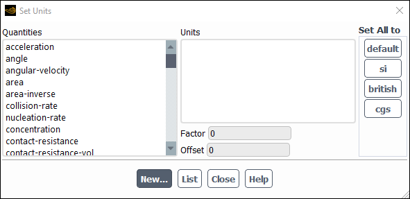
Controls
- Quantities
displays the list of all quantities used by Ansys Fluent for input and output.
- Units
lists the units appropriate for the currently selected quantity. Selecting an item in the Units list causes that unit to be used for the currently selected quantity.
- Factor
displays the conversion factor from the currently selected units to SI.
- Offset
displays the conversion offset from the currently selected units to SI.
- Set All to
contains standard sets of units that are applied to all quantities when selected.
- default
is similar to si, but uses degrees instead of radians for angles.
- si
selects the System International (SI) standard for all units.
- british
selects the English Engineering standard for all units.
- cgs
selects the CGS (centimeter-gram-second) standard for all units
- New...
opens the Define Unit Dialog Box, in which you can specify a customized unit for a particular quantity.
- List
displays the current units for all quantities in the console.
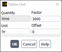
The Define Unit dialog box allows you to customize the units for a particular quantity. It is opened from the Set Units Dialog Box. For details about using this dialog box, see Defining a New Unit.
Controls
- Quantity
shows the name of the quantity for which you are defining a new unit. (You cannot edit this field; the quantity is selected in the Set Units Dialog Box.)
- Unit
sets the name for the new unit.
- Factor
sets the conversion factor from the currently selected units to SI.
- Offset
sets the conversion offset from the currently selected units to SI.
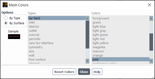
The Mesh Colors dialog box allows you to control the colors that are used
to draw meshes. It is opened from the "global"/non-persistent version of the Mesh Display Dialog Box accessed by clicking the mesh display icon ![]() . See Modifying the Mesh Colors for details about the items
below.
. See Modifying the Mesh Colors for details about the items
below.
Controls
- Options
contains options to select the method by which to set the colors.
- Color by Type
sets the color based on the type of zone.
- Color by Surface
sets the color by the zone ID. Note that if you do not like the colors assigned with this method, you can use Ctrl+Shift+O to randomize the mesh colors. Ensure the graphics window is in focus by clicking in it before using the hotkey combination (otherwise it won't work).
- Types
contains a selectable list of zone types. You can select the zone type for which you want to set the color.
- Colors
contains a list from which you can select a color for the selected type.
- Sample
displays a sample of the currently selected color.
- Reset Colors
resets the mesh colors to the default selections.