


Cell zone and boundary conditions specify the flow and thermal variables on the boundaries of your physical model. They are, therefore, a critical component of your Ansys Fluent simulations and it is important that they are specified appropriately.
In this chapter, most of the cell zones and boundary conditions will be described in detail, and an explanation of how to set them and where they are most appropriately used will be provided.
- 7.1.1. Available Cell Zone and Boundary Types
- 7.1.2. The Cell Zone and Boundary Conditions Task Pages
- 7.1.3. Changing Cell and Boundary Zone Types
- 7.1.4. Setting Cell Zone and Boundary Conditions
- 7.1.5. Copying Cell Zone and Boundary Conditions
- 7.1.6. Exporting Boundary Zones in CSV Format
- 7.1.7. Changing Cell or Boundary Zone Names
- 7.1.8. Defining Non-Uniform Cell Zone and Boundary Conditions
- 7.1.9. Defining and Viewing Parameters
- 7.1.10. Selecting Cell or Boundary Zones in the Graphics Display
- 7.1.11. Operating and Periodic Conditions
- 7.1.12. Saving and Reusing Cell Zone and Boundary Conditions
The cell zone and boundary zone types available in Ansys Fluent are classified as follows:
Table 7.1: Zone Types by Category
| Category | Zone Types |
|---|---|
| External | axis, degassing, exhaust fan, inlet vent, intake fan, interface, mass-flow inlet, mass-flow outlet, outflow, outlet vent, overset, pressure far-field, pressure inlet, pressure outlet, symmetry, velocity inlet, and wall (one-sided only) |
| Internal | fan, interior, porous jump, radiator, RANS/LES interface, and wall (two-sided only) |
| Periodic | periodic |
| Cells | fluid, solid (porous media and 3D fans are a type of fluid cell) |
Note that internal boundary zones are connected with the cells on both sides, whereas external boundary zones are connected with the cells on only one side.
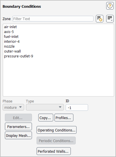
The Cell Zone Conditions and Boundary Conditions task pages (Figure 7.1: The Boundary Conditions Task Page) display lists of the zones (which can be grouped by name or zone type), and allow you to revise their settings and perform other related actions. They provide an alternate setup method to working directly in the Outline View tree.
![]() Setup →
Setup → ![]() Cell Zone Conditions
Cell Zone Conditions
![]() Setup →
Setup → ![]() Boundary Conditions
Boundary Conditions
The sections that follow explain how to perform operations, mostly using the Outline View tree, however these same operations can also be completed using the Cell Zone Conditions or Boundary Conditions task page. The sections also explain how to use the mouse and the graphics display in conjunction with the dialog box.
Note — You can modify individual boundary conditions and cell zones by expanding the Cell Zones and Boundary Conditions branches in the tree, and right-clicking the boundary condition or cell zone you want to modify.
Before you set any cell zone or boundary conditions, you should check the zone types of all boundary zones and change any if necessary. For example, if your mesh includes a pressure inlet, but you want to use a velocity inlet instead, you will need to change the pressure-inlet zone to a velocity-inlet zone. Note that external and internal boundary zones (as listed in Table 7.1: Zone Types by Category) can only be changed to a zone of the same category.
The steps for changing a zone type using the graphical user interface are as follows:
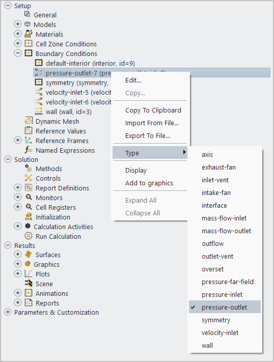
Select the boundary or cell zone in the tree (under Setup/Boundary Conditions or Setup/Cell Zone Conditions). Note that you can select multiple zones by holding the Shift or Ctrl keys when selecting, though you must ensure that all of the selections are of the same category.
Right-click a selected boundary or cell zone, and select the correct zone type from the Type sub-menu.
You can also change the zone type using either the define/boundary-conditions/zone-type or the
define/boundary-conditions/modify-zones/zone-type text command. To change the type for multiple zones of the
same category through a single action, you can enter a list of names or IDs contained within a pair of parentheses at the prompt, as
shown in the following example (which changes zone 4 and 9 to be pressure inlets):
                >
                define/boundary-conditions/zone-type
                zone id/name/list []
                (4 9)
                external-type>
                pressure-inlet
When changing the cell or boundary zone type, note the following:
For zones that have a default name (that is, <type>-<ID>, <type>_<ID>, or <type>.<ID>), the <type> in the name will be changed automatically to match the new type.
When you have a large number of internal boundary zones that you want to change to or from a wall / shadow pair, it is recommended that you change their type with a single action (either by multi-selecting in the tree or by using parentheses at the text command prompt); this will greatly reduce the processing time associated with the change.
When changing a wall / shadow pair to one of the other internal types (fan, interior, porous jump, radiator, or RANS/LES interface), you can select either the wall or the wall-shadow to change. In either case, the resulting zone will retain the ID and orientation of the wall zone and the wall-shadow zone will be deleted.
Note that you cannot use this method to change zone types to or from the periodic type, since additional restrictions exist for this boundary type. For details on creating or decoupling periodic zones, see Creating Periodic Zones and Interfaces or Decoupling Periodic Zones, respectively.
If you are using one of the general multiphase models (VOF, mixture, or Eulerian), the procedure for changing types is slightly different. See Steps for Setting Boundary Conditions for details.
In Ansys Fluent, boundary conditions are associated with zones, not with individual faces or cells. If you want to combine two or more zones that will have the same boundary conditions, see Merging Zones for information about merging zones.
To set cell zone and boundary conditions for a particular zone, perform one of the following sequences:
Right-click the name of zone in the tree (under Setup/Boundary Conditions or Setup/Cell Zone Conditions).
Select Edit....
Note: You can group Boundary Conditions based on adjacency, allowing you to see which boundaries belong to the same cell zone. To do this, right-click the Boundary Conditions branch in the Outline View tree and select Group By/Adjacency.
![]() Setup → Boundary Conditions
Setup → Boundary Conditions ![]() Group
By → Adjacency
Group
By → Adjacency
or
Select the zone from the Zone list in the Cell Zone Conditions or Boundary Conditions task page.
Click the button.
The dialog box for the selected cell or boundary zone will open, and you can specify the appropriate conditions.
Important: If you are using one of the general multiphase models (VOF, mixture, or Eulerian), the procedure for setting conditions is slightly different from that described above. See Steps for Setting Boundary Conditions for details.
You can use the text command: define/boundary-conditions/set/ to define one or more settings at a single or
multiple boundaries/cell zones of a given type. This facilitates quick and efficient setup of cell/boundary conditions for cases with
large numbers of zones.
To edit multiple boundaries you can either provide a list of boundary names / IDs enclosed in parenthesis:
                /define/boundary-conditions/set>
                wall
                (rotor-hub rotor-shroud rotor-blade-1 rotor-blade-2 stator-hub stator-shroud stator-blade-1 stator-blade-2)
zone(s) to set boundary conditions(1) [rotor-hub]
                (rotor-blade-1 rotor-blade-2)
or you can use a wildcard pattern for the boundary names:
                /define/boundary-conditions/set>
                wall
                (rotor-hub rotor-shroud rotor-blade-1 rotor-blade-2 stator-hub stator-shroud stator-blade-1 stator-blade-2)
zone(s) to set boundary conditions(1) [rotor-hub]
                (rotor-blade-*)
For additional information on formatting lists in the console, see Lists.
After entering the zone(s) you want to change you will be prompted for what setting to change. Pressing Enter will list the available settings.
When you have changed all of the desired settings, press q to exit the
define/boundary-conditions/set/<type> command. Note that some settings will not take effect until after
you have exited the command, by pressing q.
You can copy cell zones and boundary conditions from one zone to other zones of the same type. If, for example, you have several wall zones in your model and they all have the same boundary conditions, you can set the conditions for one wall, and then simply copy them to the others.
The procedure for copying cell zone or boundary conditions is as follows:
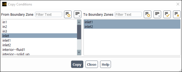
Right-click the name of zone in the tree that you want to copy (under Setup/Boundary Conditions or Setup / Cell Zone Conditions) and select Copy.... This will open the Copy Conditions dialog box (Figure 7.2: The Copy Conditions Dialog Box).
In the From Cell Zone or From Boundary Zone list, confirm that the zone that has the conditions you want to copy is selected.
In the To Cell Zones or To Boundary Zones list, select the zone or zones to which you want to copy the conditions.
Click Copy. Ansys Fluent will set all of the cell zones or boundary conditions for the zones selected in the To Cell Zones or To Boundary Zones list to be the same as the conditions for the zone selected in the From Cell Zone or From Boundary Zone list. (You cannot copy a subset of the conditions, such as only the thermal conditions.)
Note that you cannot copy conditions from external walls to internal (that is, two-sided) walls, or vice versa, if the energy equation is being solved, since the thermal conditions for external and internal walls are different.
Important: If you are using one of the general multiphase models (VOF, mixture, or Eulerian), the procedure for copying boundary conditions is slightly different. See Steps for Copying Cell Zone and Boundary Conditions for details.
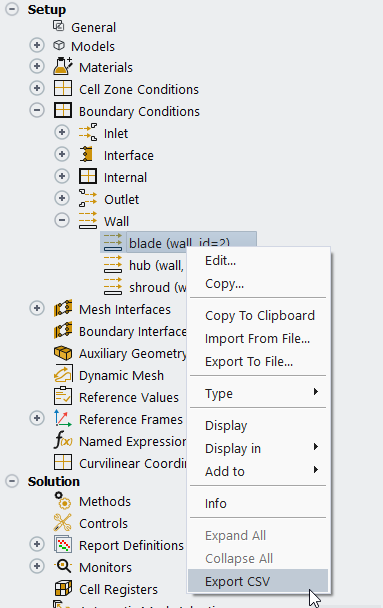
You can export a .csv file containing data from
one or more boundaries by right-clicking one or more boundaries and selecting
Export CSV.
Clicking Export CSV for one or more boundaries opens the Export Mesh Zones dialog box as shown in Figure 7.3: Export Mesh Zones Dialog Box.
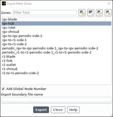
Under Zones. select the boundary zone(s) from which you would like to export mesh data.
Optionally select Add Global Node Number.
Adds the "
Global Node Number" column to the exported data. Doing so can help with the identification of shared nodes, for example, nodes shared among multiple exported surfaces. In particular, if you want the System Coupling Service to be able to identify which nodes are shared between multiple surfaces in the exported CSV data, you should select Add Global Node Number. For additional information, see System Coupling's Mapping Capabilities in the System Coupling User's Guide.Under Export boundary file name, provide a file name for the exported mesh data. Note that
.csvis appended to the name you provide.Click Export to write the
.csvto your working directory.
The same functionality is provided by entering the following command in the console and following the prompts:
/define/turbo-model/export-boundary-mesh
When exporting CSV data, the resulting .csv file contains surface meshes in a form that can be imported into CFX-Pre or CFD-Post as a user surface, or used in System Coupling mapping (see Aerodynamic Damping Analysis in the System Coupling User's Guide).
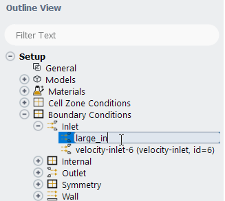
The default name for a zone is <type> - <ID> (for example, pressure-inlet-7). In some cases, you may want to assign more descriptive names to the boundary zones. If you have two pressure-inlet zones, for example, you might want to rename them small-inlet and large-inlet. (Changing the name of a zone will not change its type. Instructions for changing a zone’s type are provided in Changing Cell and Boundary Zone Types.)
You can rename boundaries and cell zones directly within the tree, by selecting the zone that you want to rename, then clicking the name (slow double-click).
Alternatively, you can rename a zone by following these steps:
Right-click the name of zone in the tree (under Setup/Boundary Conditions or Setup/Cell Zone Conditions).
Select to open the dialog box for the selected zone.
Enter a new name under Zone Name.
Click the button.
Note: If you specify a non-default name for a zone and then change its type, the name you specified will be retained; the automatic name change that accompanies a change in type occurs only for those with the default name.
Most conditions at each type of boundary zone can be defined as profile functions instead of constant values. You can use a profile contained in an externally generated profile file, or a function that you create using a user-defined function (UDF). Profiles are described in Profiles, and user-defined functions are described in the separate Fluent Customization Manual.
You can define a series of cases based on a set of parametric values. These parameters may be defined for numeric cell zone and boundary condition settings. This is especially useful if you are using Workbench and performing parametric studies (optimization), comparing cases with different boundary settings; information about such usage can be found in see Working with Parameters and Design Points in the Workbench User's Guide. If you are not running Ansys Fluent through Workbench, then you can use the parameter settings to define the same boundary condition value to different boundaries having the same units, or to use the Gradient-Based Optimizer to optimize a geometry for multiple objectives at multiple operating conditions (see Using the Gradient-Based Optimizer).
Note: For more information about using parameters with Ansys Fluent in Ansys Workbench, see Working With Input and Output Parameters in Workbench in the separate Fluent in Workbench User's Guide.
The parameters that you have defined in the various boundary condition dialog boxes are accessed by clicking the button in the Cell Zone Conditions or Boundary Conditions task page. The Parameters dialog box will open, as shown in Figure 7.4: The Parameters Dialog Box, listing all of the input parameters that you have created in the various boundary condition dialog boxes.
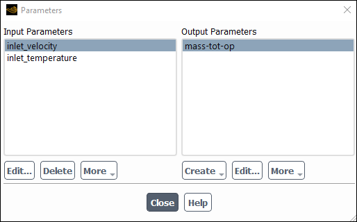
In the Parameters dialog box, under the Input Parameters list, you can
Edit the input properties using the Parameter Expression dialog box, which is the same dialog box used to create parameters. This dialog box can also be accessed by selecting New Input Parameter... from the drop-down lists in the boundary conditions dialog boxes, as described later in this section.
Important: If you are using Ansys Fluent in Ansys Workbench, you cannot edit the input parameters, you can only view them. For more information, see the separate Ansys Fluent in Ansys Workbench User's Guide.
Delete input parameters that are not assigned to a setting.
More options exist under the More drop-down list (see Working With Advanced Parameter Options):
- Use in Scheme Procedure
displays the Use Input Parameter in Scheme Procedure Dialog Box where you can apply an input parameter using a Scheme procedure.
- Use in UDF
displays the Use Input Parameter for UDF Dialog Box where you can make an input parameter available in a user-defined function.
In the Parameters dialog box, under the Output Parameters list, you can also
Create output parameters. These are single values generated by existing reports or monitors. You can generate the output parameters from report definitions (surface, volume, lift, drag, and so on). These output parameters are discussed in greater detail in Creating Output Parameters.
Edit existing output parameters.
More options exist under the More drop-down list:
- Delete
removes the selected output parameter from the list of Output Parameters.
- Rename
allows you to edit the name of the output parameter through the Rename dialog box.
- Print to Console
will output values to the console window. If you select multiple output parameters, then the output includes values from multiple output parameters.
- Print All to Console
outputs the values from all output parameters to the console window.
- Write...
allows you to store the output to a file. A dialog box is displayed allowing you to provide a file name.
- Write All...
prompts you for a file name and then writes the values for all of the output parameters to a file.
Important: Changing the units for a quantity changes the value for any input parameter using that quantity.
Note: Various Ansys Fluent setup-related input quantities (of type real and profile) can be assigned to an input parameter (indicated by the New Input Parameter... option in the corresponding drop-down list or menu next to the field). Clicking this option opens the Figure 7.6: The Parameter Expression Dialog Box where you can create the input parameter.
You can create a new cell zone or boundary condition parameter, as shown in Figure 7.5: The New Input Parameter... Selection.
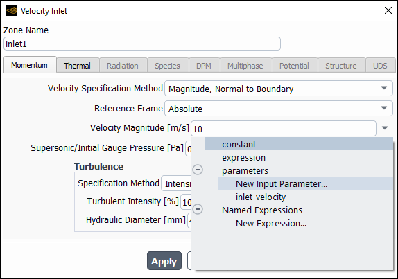
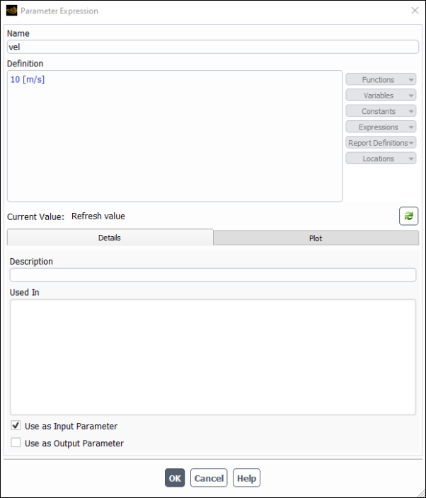
When you select New Input Parameter... from the drop-down list, the Parameter Expression dialog box (Figure 7.6: The Parameter Expression Dialog Box) will open where you will
Enter the Name of the parameter expression.
Specify the Definition as a constant.
The Used In field displays information about where the parameter is utilized. Note that this field will be populated after you create an input parameter.
Once the parameter is defined in the Parameter Expression dialog box, the name of the parameter will appear in the drop-down list of the property you are defining, as seen in Figure 7.5: The New Input Parameter... Selection.
Important: Input parameter expressions must be directly defined as a constant value including appropriate units; it may not reference another expression.
Note: Ansys Fluent automatically creates generic default names for new input and output parameters (for example,
parameter_1, parameter_2, parameter_3, and so on)
If a parameter is deleted, the default name is not reused. For example, if you have parameter_1,
parameter_2, and parameter_3, then delete
parameter_2 and create a new parameter, the default name for the new parameter will be
parameter_4.
Various Ansys Fluent setup related input quantities can be assigned to an input parameter. You can define a series of simulations based on a set of parametric values that are managed both in Ansys Fluent and in Workbench. These parameters may be defined for numeric cell zone and boundary condition settings using the New Input Parameter… option in the corresponding drop-down list or menu adjacent to a specific input setting. However, various Ansys Fluent settings are not supported by these methods.
You can mitigate this limitation using input parameters through Scheme procedures and user-defined functions (UDFs), and define input parameters for various Ansys Fluent simulation related settings.
To use a Scheme procedure with input parameters, in the Parameters dialog box under Input Parameters, select More, then choose Use in Scheme Procedure to display the Use Input Parameter in Scheme Procedure Dialog Box where you can register the input parameters that can be used in Scheme procedures during calculations. A text user interface command is also available, described in Using the Text User Interface to Define UDFs and Scheme Procedures With Input Parameters.
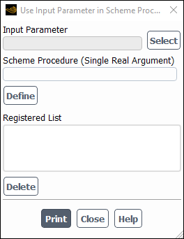
Use the Select button to open the Select Input Parameter Dialog Box where an input
parameter can be chosen. Enter a Scheme Procedure name or body starting with
lambda that should receive a real argument (the value of the selected input parameter). For example,
if the following Scheme procedure called my-funct is defined as a Scheme file that gets loaded into
the current session,
(define my-funct
	(lambda (value )
		(ti-menu-load-string (format #f "/solve/set/under-relaxation/pressure ~g" value))))
then enter my-funct for the Scheme Procedure. Otherwise, you can directly
enter the following code for the Scheme Procedure:
(lambda (value)(ti-menu-load-string (args->string '/solve/set/under-relaxation/pressure value)))
Click Define to populate the Registered List. Use Delete to delete the use of the selected input variable, but not the associated input parameter (the input parameter has to be deleted separately in the Parameters dialog box). Use Print to print out details of the registered input parameters.
Important: While writing Scheme procedures, you should use the "args->string" help procedure instead of using double quotes. For example:
(lambda ( value1)
 (display (args->string 'Changing-Theta-Divisions-value=   value1))
 (ti-menu-load-string
    (args->string '/define/models/radiation/discrete-ordinates? 'yes value1  '_  '_  '_)) )
Alternatively, you could also write:
(lambda ( value1)
 (display (args->string 'Changing-Theta-Divisions-value=  value1))
 (ti-menu-load-string
   (apply args->string `(/define/models/radiation/discrete-ordinates? yes ,value1  _  _  _) )) )
where the `
character after args->string is the grave accent character (not a single quote) and the _
character stores the default value of the current text user interface prompt. Note that the first occurrence of
value1 is the Scheme variable, while the second occurrence of value1
will be replaced by the value stored in the variable. This method eliminates the need to specify a single quote for all
arguments.
Also note that if you enter a scheme procedure body in the Use Input Parameter in Scheme Procedure dialog box, you should combine the scheme procedure lines into one single line.
To use a UDF with input parameters, in the Parameters dialog box under Input Parameters, select More, then choose Use in UDF to display the Use Input Parameter for UDF Dialog Box where you can register the input parameters that can be used in UDF functions during calculations. A text user interface command is also available, described in Using the Text User Interface to Define UDFs and Scheme Procedures With Input Parameters.
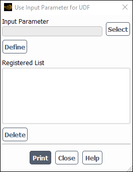
Use the Select button to open the Select Input Parameter Dialog Box where an input parameter can be chosen. Click Define to populate the Registered List. Use Delete to delete the use of the selected input variable, but not the associated input parameter (the input parameter has to be deleted separately in the Parameters dialog box). Click Print to print out the parameter ID of the registered input parameter. This ID should be used to access the value of the parameter in UDF.
By registering the input parameter, Ansys Fluent knows that this input parameter is being used by a UDF. In the UDF C function,
you can access the registered input parameter value using the RP_Get_Input_Parameter macro. For
example,
real value = RP_Get_Input_Parameter(“real-4”),
where real-4 is an input parameter ID obtained using the Print feature.
The /define/parameters/input-parameters/advance/use-in text interface command can also be used to
define input parameters and Scheme procedures and user-defined functions.
The Scheme procedures can use other text user interface (TUI) commands in Ansys Fluent to change the desired simulation settings in a parametric manner. Each numerical component of the TUI command string can be marked and treated as a parameter. Setting up advanced input parameters requires using Scheme functions that use text interface commands to apply new values. Once defined, these input parameters are displayed in the Parameters dialog box alongside other input parameters. The input parameter passes a constant numeric value to the registered/provided Scheme function. Therefore, the associated Scheme function (and corresponding Ansys Fluent text command) uses the constant parameter values using the units that were already defined for the designated text command quantity.
-
/define/parameters/input-parameters/advance Enter the advanced input parameters menu.
-
use-in/ Allows you to use an input parameter in a Scheme procedure or in a UDF. The following examples demonstrates how to use an input parameter using a Scheme procedure. The Scheme procedure body can be written at the prompt itself:
/define/parameters/input-parameters/advance>use-inSelect type:>scheme-procName of parameter ["parameter-1"] parameter-1 value [0]0.3Enter the name/body of apply-function [()](lambda (value ) (ti-menu-load-string (format #f "/solve/set/under-relaxation/pressure ~g" value)))or it can be written in a Scheme file (for example,
my-funct)/define/parameters/custom-input-parameters>use-inSelect type:>scheme-procName of parameter ["parameter-1"] parameter-1 value [0]0.3Enter the name/body of apply-function [()]my-functwhere the
my-functScheme file contents are:(define my-funct (lambda (value ) (ti-menu-load-string (format #f "/solve/set/under-relaxation/pressure ~g" value))))The following example demonstrates how to use an input parameter using a UDF:
/define/parameters/input-parameters/advance>use-inSelect type:>udf-sideName of parameter ["parameter-1"] parameter-1 value [0]0.3-
delete Deletes the use of the selected input variable, but not the associated input parameter (the input parameter has to be deleted separately). Using the wildcard ‘*’ allows you to delete all custom input variable at once.
-
list Shows usage of input parameters for Scheme procedures and for UDFs
-
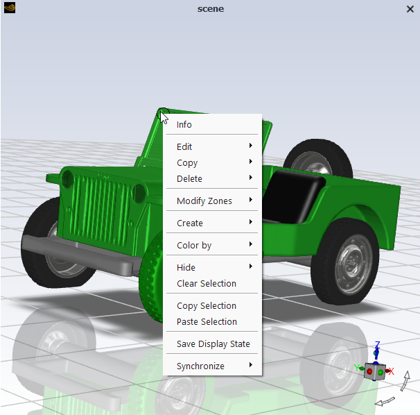
During setup you will want to display boundary conditions, which can be accomplished using the Mesh Display Dialog Box. You also have the option to highlight boundaries in the tree, right-click them, and select Display, Display in or Add to. This feature is particularly useful if you are setting up a problem for the first time or if you want to visually confirm the location of a particular boundary condition.
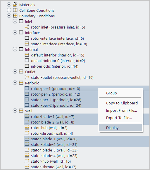
The boundary description in the tree includes the zone IDs, which can help you differentiate the zones. You can also right-click selected boundaries in the graphics window to perform a number of options including printing information about the boundaries (surface IDs, zone IDs, surface groups, and so on), fusing zones, and creating graphics objects. For example, refer to Figure 7.10: Example Operations for Multiple Selected Surfaces in the Graphics Window, which shows some operations that are available for the selected surfaces (highlighted in light green).
The Cell Zone Conditions and Boundary Conditions task pages allow you to access the Operating Conditions dialog box, where you can set the operating pressure, reference pressure location, include the effects of gravity, and specify other operating variables, as discussed in Modeling Basic Fluid Flow.
![]() Setup →
Setup → ![]() Cell Zone Conditions →
Operating Conditions...
Cell Zone Conditions →
Operating Conditions...
![]() Setup →
Setup → ![]() Boundary Conditions → Operating
Conditions...
Boundary Conditions → Operating
Conditions...
The Periodic Conditions dialog box can be accessed from the Boundary Conditions task page. For a detailed description of this dialog box’s inputs, refer to Periodic Flows.
![]() Setup →
Setup → ![]() Boundary Conditions → Periodic
Conditions...
Boundary Conditions → Periodic
Conditions...
You can save cell zone and boundary conditions to a file so that you can use them to specify the same conditions for a different case, as described in Reading and Writing Boundary Conditions.