


For an incompressible flow or (for a steady-state case) a compressible flow in a cell zone or cell zone group that does not involve any pressure boundaries, Ansys Fluent can adjust the gauge pressure field after each iteration to keep it from floating. This is done using the pressure in the cell located at or nearest to the reference pressure location. The pressure value in this cell is subtracted from the entire gauge pressure field; as a result, the gauge pressure at the reference pressure cell is always zero.
Note: When you patch the pressure field for an incompressible flow or steady-state compressible flow, the reference pressure is subtracted in any closed domain after the patching. Therefore, the pressure field will be altered from your specified values.
By default, Fluent uses a reference pressure method that is designed for a mix of connected and disconnected fluid zones. Zones are considered connected if fluid can pass between them; this is the case when the zones are contiguous through boundary zones of type interior, fan, porous-jump, radiator, rans-les-interface, or overset, or share a mesh interface. A unique reference pressure cell will be used in each group of connected zones, and the presence of a pressure boundary in one group will not disqualify other groups from having the pressure adjusted.
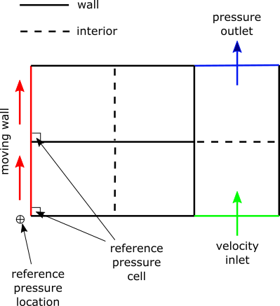
An example of connected and disconnected fluid zones is shown in the following figure. Here, two lid-driven cavities are on the left, each consisting of a group of two cell zones enclosed by walls; there is also a channel on the right made up of two cell zones, which includes a pressure outlet. Fluent identifies reference pressure cells only in the left groups, and subtracts a unique value from the gauge pressure field within each of these groups. The gauge pressure field for the group on the right is not adjusted.
The reference pressure cell of a particular group is the one that is at or closest to the reference pressure location. By default, this reference pressure location is defined as (0,0,0). There may be cases in which you might want to move the reference pressure location, perhaps locating it at a point where the absolute static pressure is known (for example, if you are planning to compare your results with experimental data). To change the location, enter new (X,Y,Z) coordinates for Reference Pressure Location in the Operating Conditions Dialog Box.
![]() Setup →
Setup → ![]() Cell Zone
Conditions → Operating Conditions...
Cell Zone
Conditions → Operating Conditions...
You can use the following text command to print the center coordinates of the reference pressure cells and the number of cell groups formed, the number of groups that will undergo pressure adjustment, and the cell zone IDs within each group:
define →
operating-conditions →
used-ref-pressure-location
Prior to Release 2020 R2, the default reference pressure method assumed that all of the cell zones are connected, which means that a single reference pressure cell is used in all of the zones, and the pressure adjustment is not performed anywhere if a pressure boundary exists in the case. For case files that were set up in such earlier releases, you can ensure that the reference pressure method accounts for connected and disconnected fluid zones (and thus always results in the most accurate static pressure calculations) by entering the following text command:
define →
operating-conditions → reference-pressure-method
2