


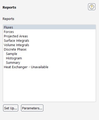
The Reports task page allows you to set up reports for your CFD simulation. Reports can be compiled for fluxes, forces, projected areas, surface and volume integrals, among others. See Reporting Alphanumeric Data for more information.
Controls
- Reports
displays a list of available report types in Ansys Fluent.
You can double-click an item in the Reports list to open the corresponding dialog box, or you can select the item in the list and click the Set Up... button.
- Fluxes
selecting this item and clicking the Set Up... button opens the Flux Reports Dialog Box.
- Forces
selecting this item and clicking the Set Up... button opens the Force Reports Dialog Box.
- Projected Areas
selecting this item and clicking the Set Up... button opens the Projected Surface Areas Dialog Box.
- Surface Integrals
selecting this item and clicking the Set Up... button opens the Surface Integrals Dialog Box.
- Volume Integrals
selecting this item and clicking the Set Up... button opens the Volume Integrals Dialog Box.
- Discrete Phase
allows you to report on one of the following three report types:
- Sample
selecting this item and clicking the Set Up... button opens the Sample Trajectories Dialog Box.
- Histogram
selecting this item and clicking the Set Up... button opens the Trajectory Sample Histograms Dialog Box.
- Summary
selecting this item and clicking the Set Up... button opens the Particle Summary Dialog Box.
- Heat Exchanger
selecting this item and clicking the Set Up... button opens the Heat Exchanger Report Dialog Box.
- Set Up...
opens the dialog box corresponding to the selected item in the Reports list.
- Parameters...
opens the Parameters Dialog Box.
For additional information, see the following sections:
- 51.20.1. Flux Reports Dialog Box
- 51.20.2. Force Reports Dialog Box
- 51.20.3. Projected Surface Areas Dialog Box
- 51.20.4. Surface Integrals Dialog Box
- 51.20.5. Volume Integrals Dialog Box
- 51.20.6. Sample Trajectories Dialog Box
- 51.20.7. Trajectory Sample Histograms Dialog Box
- 51.20.8. Particle Summary Dialog Box
- 51.20.9. Heat Exchanger Report Dialog Box
- 51.20.10. Parameters Dialog Box
- 51.20.11. Use Input Parameter in Scheme Procedure Dialog Box
- 51.20.12. Use Input Parameter for UDF Dialog Box
- 51.20.13. Rename Dialog Box
- 51.20.14. Parameter Expression Dialog Box
- 51.20.15. Save Output Parameter Dialog Box
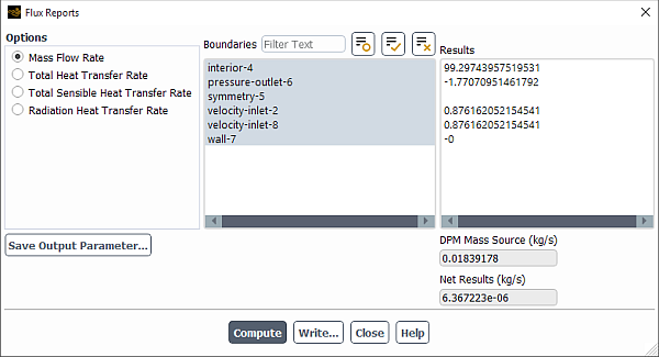
The Flux Reports dialog box allows you to compute the mass flow rate, heat transfer rate, and radiation heat transfer rate on selected boundary zones. See Fluxes Through Boundaries for details.
Controls
- Options
contains the following option buttons:
- Mass Flow Rate
specifies that the mass flow rate is computed for the selected boundary zones.
- Total Heat Transfer Rate
specifies that the total heat transfer rate is computed for the selected boundary zones.
- Total Sensible Heat Transfer Rate
specifies that the total sensible heat transfer rate is computed for the selected boundary zones. It reports the total energy flux as defined in Equation 5–5 in the Theory Guide.
- Radiation Heat Transfer Rate
specifies that the radiation heat transfer rate is computed for the selected boundary zones.
- Pressure Work Rate
specifies that the pressure work rate is computed for the selected boundary zones. This rate is the energy transfer due to pressure when a fluid zone undergoes normal zone motion relative to an adjacent solid zone (for further details, see Equation 25–1 in the Theory Guide). This pressure work is on the fluid side only, not on the solid side. This option is only available when the energy equation is enabled, the absolute velocity formulation is selected, and the Frame Motion and/or Mesh Motion option is enabled in the Fluid dialog box.
- Viscous Work Rate
specifies that the viscous work rate is computed for the selected boundary zones, which is the integral of the product of viscous stress with velocity over the external boundary of the domain with the boundary normal directed inside (for further details, see Equation 25–2 in the Theory Guide). Note that after reading case and data files into Ansys Fluent, the viscous work rate is zero. You need to run at least one iteration or time step to obtain the viscous work rate value. This item is available only when the energy equation is enabled and the pressure-based solver is selected.
- Film Mass Flow Rate
specifies that the mass flow rate is computed for the selected boundary zone(s). This option is available only when the Eulerian wall film model is enabled.
- Film Heat Transfer Rate
specifies that the film heat transfer rate is computed for the selected boundary zone(s). This option is available only when the Eulerian wall film model is enabled.
- Electric Current Rate
specifies that the electric current rate is computed for the selected boundary zone(s). This option is available only if the potential equation is enabled—see Modeling Electric Potential Field and Electrochemistry Models.
- Save Output Parameter...
opens the Save Output Parameter Dialog Box.
- Boundaries
contains a selectable list of valid boundary zones for flux reporting.
- Results
displays the results of the selected flux computation for each boundary zone selected. The summation of the individual zone flux results is displayed in the box below the Results list.
- Compute
computes the flux for each of the selected boundary zones and updates Net Results (for example, in kg/s, W, and so on) and other reports, for example, Heat of Reaction Source.
- Write...
opens the Select File dialog box (The Select File Dialog Box), which you can use to save the reported values to a file.
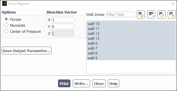
The Force Reports dialog box allows you to compute the forces along a specified vector, moments about a specified center, and the coordinates of the center of pressure for selected wall zones. See Forces on Boundaries for details.
Controls
- Options
contains option buttons that control computation of the forces, moments, or center of pressure.
- Forces
enables the computation of the pressure and viscous forces.
- Moments
enables the computation of the pressure and viscous moments.
- Center of Pressure
enables the computation of the coordinates about which the moment by pressure forces is zero.
- Direction Vector
contains the components of the force vector. This label is visible when the Forces option button is active.
- X,Y,Z
are the components of the force vector along which the forces will be computed.
- Moment Center
contains the Cartesian coordinates of the moment center. This label is visible when the Moments option button is active.
- X,Y,Z
are the Cartesian coordinates of the moment center about which moments will be computed.
- Moment Axis
contains the Cartesian coordinates of the moment axis. This label is visible when the Moments option button is active.
- X,Y,Z
are the Cartesian coordinates of the moment axis about which moments will be computed.
- Coordinate
contains the value of the Cartesian coordinate that is fixed. This label is visible when the Center of Pressure option button is active.
- X,Y,Z
are the Cartesian coordinates, one of which will be fixed.
- Value (n)
is the point where the selected Cartesian coordinate will be fixed.
- Wall Zones
contains a selectable list of wall zones and porous zones (when applicable). The force or moment information is printed for each zone, and then a total force or moment for all the zones is presented.
- Save Output Parameter...
opens the Save Output Parameter Dialog Box.
displays (in the console) the pressure, viscous (if appropriate), and total forces or moments, and the pressure, viscous, and total force coefficients along the specified force vector or moment center for the selected wall zones. The center of pressure coordinates will print to the console when the Center of Pressure option is activated.
- Write...
opens The Select File Dialog Box, which you can use to save the reported values to a file.
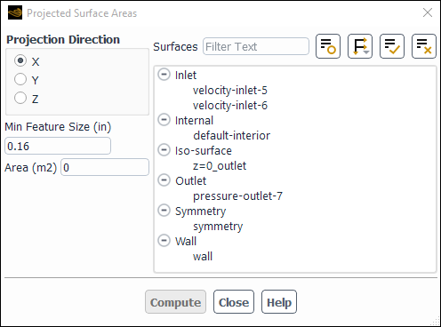
The Projected Surface Areas dialog box
allows you to compute an estimated area of the projection of selected
surfaces along the  ,
,  , or
, or  axis. See Projected Surface Area Calculations for details.
Controls
- Projection Direction
indicates the direction along which to project the surface.
- Min Feature Size
specifies the length of the smallest feature in the geometry that you want to resolve in the area calculation.
- Area
displays the computed projected area.
- Surfaces
contains a list of existing surfaces. You can select the surface(s) for which the projected area is to be calculated in this list.
- Compute
computes the area of the selected surfaces projected along the selected direction. The area will be printed in the Area box and in the console window.
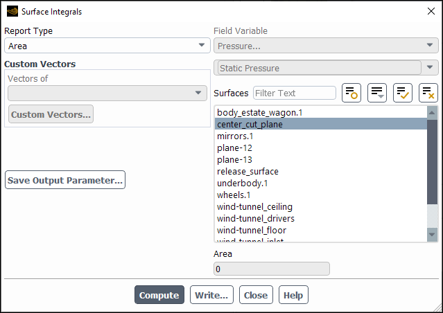
The Surface Integrals dialog box allows you to compute the area, mass and volume flow rate, standard deviation, integral, flow rate, area-weighted average, custom vector-based flux, custom vector flux, custom vector-weighted average, mass-weighted average, sum, facet average, facet minimum/maximum, uniformity index (weighted by area or mass), vertex average, or vertex minimum/maximum quantity of a specified field variable on a selected list of surfaces. See Surface Integration for details.
Controls
- Report Type
contains drop-down list that has options that control the method of surface integration.
- Area
turns on the computation of the surface area.
- Area-Weighted Average
turns on the computation of the area-weighted average on the surface(s).
- Custom Vector Based Flux
turns on the computation of the vector-based flow rate of a quantity through the surface(s).
- Custom Vector Flux
turns on the computation of the flow rate on a vector through the surface(s).
- Custom Vector Weighted Average
turns on the computation of vector-weighted average of a quantity on the surface(s).
- Facet Average
turns on the computation of the facet-averaged quantity on the surface(s).
- Facet Minimum
turns on the computation of the facet minimum of a quantity on the surface(s).
- Facet Maximum
turns on the computation of the facet maximum of a quantity on the surface(s).
- Flow Rate
turns on the computation of the flow rate through the surface(s).
- Integral
turns on the computation of the integral on the surface(s).
- Mass Flow Rate
turns on the computation of the mass flow rate through the surface(s).
- Mass-Weighted Average
turns on the computation of the mass-averaged quantity on the surface(s).
- Standard Deviation
turns on the computation of the standard deviation of a specified field variable on a surface.
- Sum
turns on the computation of the summed quantity on the surface(s).
- Uniformity Index - Mass Weighted
turns on the computation of the mass-weighted uniformity index of a quantity on the surface(s).
- Uniformity Index - Area Weighted
turns on the computation of the area-weighted uniformity index of a quantity on the surface(s).
- Vertex Average
turns on the computation of the vertex-averaged quantity on the surface(s).
- Vertex Minimum
turns on the computation of the vertex minimum of a quantity on the surface(s).
- Vertex Maximum
turns on the computation of the vertex maximum of a quantity on the surface(s).
- Volume Flow Rate
turns on the computation of the volume flow rate through the surface(s).
- Custom Vectors
allows you to define custom vectors if you selected Custom Vector Based Flux, Custom Vector Flux, or Custom Vector Weighted Average from the Report Type drop-down list.
- Field Variable
contains a list of the field variables that can be used in the surface integrations. This option is not active if the Area, Mass Flow Rate, or Volume Flow Rate option is active.
- Surfaces
is a selectable list of surfaces.
- Area
displays the result of the area summation over all the selected surfaces. This label is visible when Area is active.
- Area-Weighted Average
displays the result of the area-weighted average computation over all the selected surfaces. This label is visible when Area-Weighted Average is active.
- Average of Facet Values
displays the result of the facet-averaged computation over all the selected surfaces. This label is visible when Facet Average is active.
- Minimum of Facet Values
displays the minimum facet value on all the selected surfaces. This label is visible when Facet Minimum is active.
- Maximum of Facet Values
displays the maximum facet value on all the selected surfaces. This label is visible when Facet Maximum is active.
- Flow Rate
displays the result of the flow rate computation over all the selected surfaces. This label is visible when Flow Rate is active.
- Integral
displays the result of the integral computation over all the selected surfaces. This label is visible when Integral is active.
- Mass Flow Rate
displays the result of the mass flow rate computation over all the selected surfaces. This label is visible when Mass Flow Rate is active.
- Mass-Weighted Average
displays the result of the mass-averaged computation over all the selected surfaces. This label is visible when Mass-Weighted Average is active.
- Standard Deviation
displays the result of the standard deviation computation over all the selected surfaces. This label is visible when Standard Deviation is active.
- Sum of Facet Values
displays the result of the summation over all the selected surfaces. This label is visible when Sum is active.
- Uniformity Index Mass-Wt.
displays the mass-weighted uniformity index value on all the selected surfaces. This label is visible when Uniformity Index - Mass Weighted is active.
- Uniformity Index Area-Wt.
displays the area-weighted uniformity index value on all the selected surfaces. This label is visible when Uniformity Index - Area Weighted is active.
- Average of Surface Vertex Values
displays the result of the vertex-averaged computation over all the selected surfaces. This label is visible when Vertex Average is active.
- Minimum of Vertex Values
displays the minimum facet value on all the selected surfaces. This label is visible when Vertex Minimum is active.
- Maximum of Vertex Values
displays the maximum facet value on all the selected surfaces. This label is visible when Vertex Maximum is active.
- Volumetric Flow Rate
displays the result of the volumetric flow rate computation over all the selected surfaces. This label is visible when Volume Flow Rate is active.
- Save Output Parameter...
opens the Save Output Parameter Dialog Box.
- Compute
computes the specified integration on the selected surfaces.
- Write...
opens The Select File Dialog Box, which you can use to save the reported values to a file.
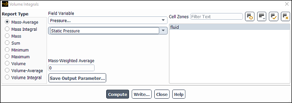
The Volume Integrals dialog box allows you to compute the volume, sum, maximum, minimum, volume integral, volume-averaged quantity, mass integral, or mass-averaged quantity of a specified field variable on a selected list of cell zones. See Volume Integration for details.
Controls
- Report Type
contains option buttons that control the method of volume integration.
- Mass-Average
turns on the computation of the mass-averaged quantity on the cell zone.
- Mass Integral
turns on the computation of the mass integral on the cell zone.
- Mass
turns on the computation of the total mass in the cell zone for the selected phase.
- Sum
turns on the computation of the summation over all cells in the selected zone.
- Sum*2Pi
computes the summation over all cells in the selected zone of a 2D axisymmetric model and multiplies the result by 2π to give the summation over the revolved domain. This option is only available in 2D axisymmetric cases.
- Minimum
computes the minimum value of the selected variable at each cell in the selected zone.
- Maximum
computes the maximum value of the selected variable at each cell in the selected zone.
- Volume
turns on the computation of the cell zone volume.
- Volume Integral
turns on the computation of the volume integral on the cell zone.
- Volume-Average
turns on the computation of the volume-weighted average on the cell zone.
- Field Variable
contains a list of the field variables that can be used in the sum, volume integral, and average computations. This option is not active if the Volume option is active.
- Cell Zones
is a selectable list of cell zones.
- Total Volume
displays the result of the volume computation over all the selected zones. This label is visible when Volume is active.
- Sum
displays the result of the summation over all the selected zones. This label is visible when Sum is active.
- Sum *2Pi
displays the result of the summation over all the selected zones multiplied by 2π. This label is visible when Sum*2Pi is active.
- Max
displays the result of the maximum value of the selected zone(s). This label is visible when Maximum is active.
- Min
displays the result of the minimum value of the selected zone(s). This label is visible when Minimum is active.
- Total Volume Integral
displays the result of the volume-integral computation over all the selected zones. This label is visible when Volume Integral is active.
- Volume-Weighted Average
displays the result of the volume-averaged computation over all the selected zones. This label is visible when Volume-Average is active.
- Total Mass-Weighted Integral
displays the result of the mass-integral computation over all the selected zones. This label is visible when Mass Integral is active.
- Mass-Weighted Average
displays the result of the mass-averaged computation over all the selected zones. This label is visible when Mass-Average is active.
- Save Output Parameter...
opens the Save Output Parameter Dialog Box.
- Compute
computes the specified integration on the selected zones.
- Write...
opens The Select File Dialog Box, which you can use to save the reported values to a file.
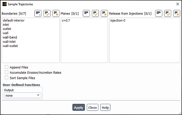
The Sample Trajectories dialog box allows the writing of particle states (position, velocity, diameter, temperature, and mass flow rate) at various boundaries and planes (lines in 2D). See Sampling of Trajectories for details about the items below.
Controls
- Boundaries
lists boundaries that can be chosen as the surfaces at which samples will be written.
- Lines
(in 2D) lists lines that can be chosen as the surfaces at which samples will be written.
- Planes
(in 3D) lists planes that can be chosen as the surfaces at which samples will be written.
- Release From Injections
lists injections from which the injection to be tracked is chosen.
- Append Files
causes the results of multiple calculations to be appended to a single file.
- Accumulate Erosion/Accretion Rates
causes erosion and accretion rates to be accumulated for repeated trajectory calculations.
- Sort Sample Files
causes the sample files to be sorted by injection and particle ID for steady tracking or simulated time (
flow-timein the 13th column) for unsteady tracking. The latter is required if the sample file is to be used as an unsteady injection file.- User-Defined Functions
allow control of the format and the information written for the sample output.
- Output
contains a drop-down list of available user-defined functions.
- Compute
causes the particles to be tracked and their status to be written to files when they encounter selected surfaces. This button will not appear for unsteady particle tracking.
- Start
initiates sampling for unsteady particle tracking. This button will replace the Compute button if you are performing unsteady particle tracking. After you click it, it will change to the Stop button. Click Stop to stop the sampling. (The label will change back to Start.)
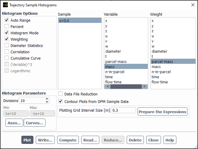
The Trajectory Sample Histograms dialog box allows the plotting of histograms from sample files created in the Sample Trajectories Dialog Box. See Histogram Reporting of Samples for details about the items below.
Controls
- Options
contains check buttons for histogram options.
- Auto Range
toggles between automatic and manual settings of the histogram range.
- Percent
causes the plot to indicate the percent of particles. Deselecting this will result in the actual number of particles being plotted.
- Histogram Mode
allows you to display the histogram with or without bars.
- Weighting
allows you to apply a weight to the data sample.
- Diameter Statistics
allows you to display a summary of diameter statistics for a selected variable in the console window.
- Correlation
allows you to choose correlations between how one particle variable depends on another particle variable.
- Cumulative Curve
allows you to compute a cumulative distribution curve for a selected variable.
- (Variable^3)
allows you to plot the cumulative mass distribution for a constant particle density using the particle diameter.
- Histogram Parameters
contains controls for histogram plotting.
- Divisions
sets the number of "bins" in the histogram.
- Min
displays the minimum value of the variable selected in the Variable list. If Auto Range is off, you can set the minimum by typing a new value.
- Max
displays the maximum value of the variable selected in the Fields list. If Auto Range is off, you can set the maximum by typing a new value.
- Axes...
opens the Axes Dialog Box, which allows you to customize the histogram axes.
- Curves...
opens the Curves Dialog Box, which allows you to customize the curves used in the histogram.
- Sample
lists the data samples that have been read in.
- Variable
lists the fields variables available in the selected sample.
- Scale, No. of Bins
is an informational list that displays the scaling and the number of bins for each variable in the selected sample. This list is displayed only if Data File Reduction is selected.
- Weight
lists the weighted fields variables available in the selected sample.
- Correlation
lists the sampled variables, allowing you to choose the correlation variable.
- Data File Reduction
enables the reduction of injection data in the selected sample and expands the dialog box to show inputs for Data Reduction Settings For Selected Variables and Data Reduction Options. For information about available data reduction settings, see Data Reduction of Samples.
- Contour Plots from DPM Sample Data
allows you to generate named expressions from a sample file in order to use them for graphical postprocessing (contour plotting) on the surface where the DPM particles were sampled. For details, see Contour Plots of DPM Particle Sampling Results on a Planar Surface.
- Plot
displays the histogram in the active graphics window.
- Write...
stores the histograms in an XY-plot file format
- Compute
updates the Min and Max values.
- Read...
opens The Select File Dialog Box, where you can select a sample file to be read.
- Reduce...
reduces sample data in the selected sample. For more information, see Data Reduction of Samples. This button is available only if Data File Reduction is selected.
- Delete
removes the sample selected in the Sample list.
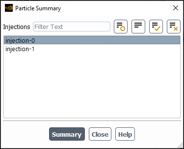
The Particle Summary dialog box allows you to report a summary for particle injections. See Summary Reporting of Current Particles for details about the items below.
Controls
- Injections
lists the particle injection(s) for which you can generate a summary.
- Summary
prints the injection summary in the console window.
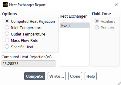
The Heat Exchanger Report dialog box allows you to report a summary for heat exchangers. See Postprocessing for the Heat Exchanger Model for details about the items below.
Controls
- Options
lists the available reporting options for the heat exchanger.
- Computed Heat Rejection
allows you to report the heat rejection calculated from the heat exchanger.
- Inlet Temperature
allows you to report the inlet temperature for both the primary and the auxiliary heat exchanger fluid.
- Outlet Temperature
allows you to report the outlet temperature for both the primary and the auxiliary heat exchanger fluid.
- Mass Flow Rate
allows you to report the mass flow rate for both the primary and the auxiliary heat exchanger fluid.
- Specific Heat
allows you to report the specific heat for both the primary and the auxiliary heat exchanger fluid.
- Result
displays the results of the calculations once the Compute button is selected.
- Heat Exchanger
displays a list of heat exchanger fluid zones
- Fluid Zone
(not available when Computed Heat Rejection option is selected.) allows you to report quantities for either the primary or auxiliary fluid zones.
- Compute
computes the specified quantity on the selected zones.
- Write...
opens The Select File Dialog Box, which you can use to save the reported values to a file.
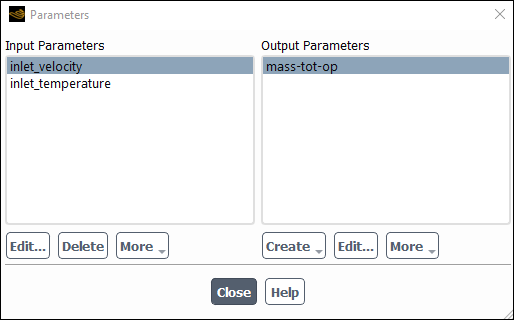
The Parameters dialog box allows you to create input parameters (in Scheme or user-defined function procedures only) and output parameters, which allow you to compare reporting values for different cases, or include reporting values in the function minimized by the mesh morpher/optimizer. See Creating Output Parameters for details about the items below.
Controls
- Input Parameters
contains a list of existing input parameters. See Defining and Viewing Parameters for details about creating input parameters.
- Edit...
opens the Parameter Expression Dialog Box.
Important: When using Ansys Fluent in Ansys Workbench, parameters are not editable, so the Edit... button becomes the View... button. This opens the Parameter Expression Dialog Box where the parameter properties can only be viewed. For more information, see the separate Ansys Fluent in Workbench User’s Guide.
- Delete
removes the selected input parameter from the list of Input Parameters.
- More
contains a drop-down list that allows more advanced use of input parameters. Available options include:
- Use in Scheme Procedure
opens the Use Input Parameter in Scheme Procedure Dialog Box.
- Use in UDF
opens the Use Input Parameter for UDF Dialog Box.
- Output Parameters
contains a list of existing output parameters.
- Create
opens the Report Definitions Dialog Box, allowing you to create additional output parameters based on report definitions.
- Edit...
opens the dialog box corresponding to the selected item in the Output Parameters list.
- More
contains a drop-down list containing additional tasks that you can perform, including:
- Delete
removes the selected output parameter from the list of Output Parameters.
- Rename
allows you to rename the selected output parameter.
- Print to Console
reports values to the console window. If you select multiple output parameters, then the output includes values from multiple output parameters.
- Print All to Console
outputs the values from all output parameters to the console window.
- Write...
allows you to store the output to a file. A dialog box is displayed allowing you to provide a file name.
- Write All...
prompts you for a file name and then writes the values for all of the output parameters to a file.
Note: Ansys Fluent automatically creates generic default names for
new input and output parameters (for example, parameter-1, parameter-2, parameter-3, and so on) If a parameter is deleted, the default name is not reused.
For example, if you have parameter-1, parameter-2, and parameter-3, then delete parameter-2 and create a new
parameter, the default name for the new parameter will be parameter-4.
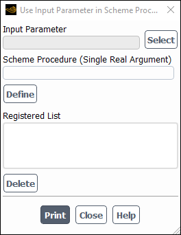
The Use Input Parameter in Scheme Procedure dialog box allows you to use the input parameter in a Scheme procedure. In turn, this Scheme procedure can also use text user interface (TUI) commands. For more information, see Working With Advanced Parameter Options.
Controls
- Input Parameter
contains the name of an input parameter.
- Select
opens the Select Input Parameter Dialog Box where an input parameter can be chosen.
- Scheme Procedure (Single Real Argument)
contains a procedure name (if already defined using a Scheme file) or procedure body written in the Scheme language using
lambda. This procedure should receive one real argument.- Define
registers the selected input parameter.
- Registered List
contains a list of registered input parameters.
- Delete
removes a selected registered input parameter from the list.
prints details of the registered input parameters.
The Use Input Parameter for UDF dialog box allows you to select the input parameters that can be used inside a user-defined function (UDF) during calculations.
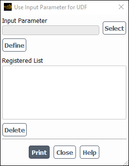
Controls
- Input Parameter
contains the name of an input parameter.
- Select
opens the Select Input Parameter Dialog Box where an input parameter can be chosen.
- Define
registers the selected input parameter.
- Registered List
contains a list of registered input parameters.
- Delete
removes a selected registered input parameter from the list.
prints the ID of the registered input parameters. The ID values are used to access the value of the parameter in the user-defined function.
The Rename dialog box allows you to change the name of the output parameter that you created.
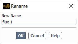
Controls
- New Name
contains the new name of the output parameter.
The Parameter Expression dialog box allows you to create input parameters, which can be used to run a case and vary the value of the input to explore how the results change.
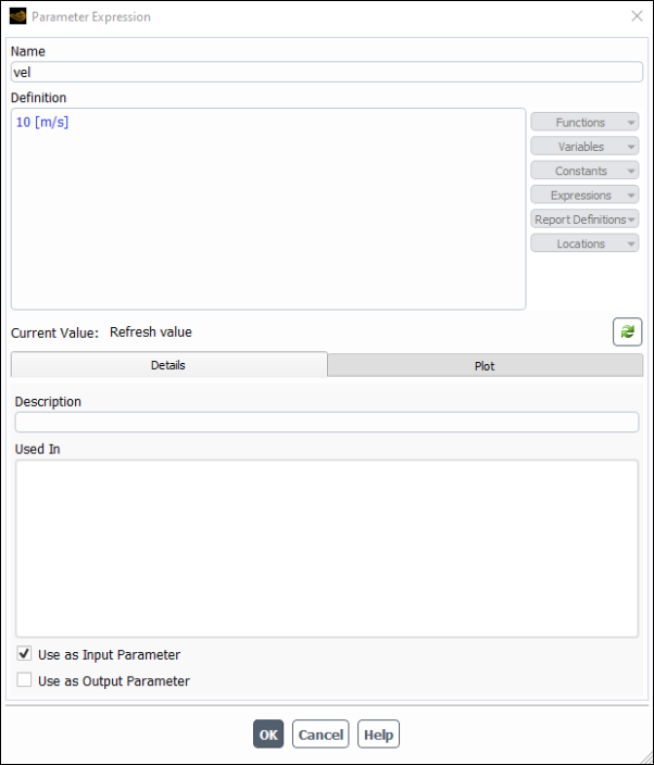
Controls
- Name
contains the name of the input parameter expression.
- Definition
contains the current value of the input parameter.
- Used In
indicates the cell zone or boundary condition where the input parameter is currently used. The relevant zone or boundary condition will be displayed after you create an input parameter.
Important: Input parameter expressions must be directly defined as a constant value including appropriate units; it may not reference another expression.
Note: Ansys Fluent automatically creates generic default names for new input and output parameters
(for example, parameter_1, parameter_2,
parameter_3, and so on) If a parameter is deleted, the default name is
not reused. For example, if you have parameter_1,
parameter_2, and parameter_3, then delete
parameter_2 and create a new parameter, the default name for the new
parameter will be parameter_4.
The Save Output Parameter dialog box allows you to save specific output parameters that allow you to compare reporting values for different cases. See Creating Output Parameters for details about the items below.
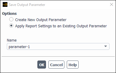
Controls
- Options
contains options for saving your output parameters.
- Create New Output Parameter
allows you to create a new output parameter.
- Apply Report Settings to an Existing Output Parameter
allows you to overwrite an existing output parameter of the same type.
- Name
contains the name for the current output parameter.
Note: Ansys Fluent automatically creates generic default names for
new input and output parameters (for example, parameter-1, parameter-2, parameter-3, and so on) If a parameter is deleted, the default name is not reused.
For example, if you have parameter-1, parameter-2, and parameter-3, then delete parameter-2 and create a new
parameter, the default name for the new parameter will be parameter-4.