As described in Embedded Large Eddy Simulation (ELES) in the Theory Guide, the Embedded Large Eddy Simulation model is used when modeling a smaller embedded LES zone within a larger RANS computational domain. Recall that the interface between the upstream RANS zone and the LES zone must be defined (by assigning the interface to a velocity fluctuation algorithm). In addition, the interface between the LES zone and the downstream RANS zone must be considered.
This section describes how to set up the Embedded Large Eddy Simulation model.
In the Viscous Model dialog box, enable any RANS model (for example,
 -
- ,
,  -
- ), or you can select DES, SAS, SDES, or SBES. The only RANS
model not compatible with ELES is the Spalart-Allmaras model, as a
one-equation model cannot provide the required turbulent length scale to the
interface method.
), or you can select DES, SAS, SDES, or SBES. The only RANS
model not compatible with ELES is the Spalart-Allmaras model, as a
one-equation model cannot provide the required turbulent length scale to the
interface method. If a RANS model is selected, the model is applied globally to the computational domain, however, values for turbulence variables are frozen within the ELES region. The frozen state of the ELES zone is used to determine the flow conditions (for
 -
- ,
,  -
- , and so on) at the downstream LES-RANS zone interface.
Note that this approach requires a fairly well converged global RANS
solution to start with.
, and so on) at the downstream LES-RANS zone interface.
Note that this approach requires a fairly well converged global RANS
solution to start with.If DES, SAS, SDES, or SBES is used in the outer zone, these models are not frozen, but run in the background in the ELES region, obtaining proper flow conditions (for
 -
- ,
,  -
- , etc.) at the downstream LES-RANS zone interface.
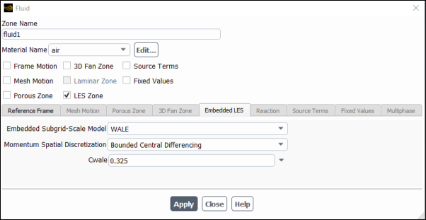
 For the specified fluid cell zone, enable LES Zone in the Fluid dialog box (Figure 15.28: Specifying an ELES Zone in the Fluid Dialog Box). This enables the Embedded LES tab in the Fluid dialog box.
Note: When DES, SAS, SDES, or SBES is used for the global model, this and the next step can, but need not, be skipped. (Remember the general limitations of DES in free, wall-independent flows.) If you choose to skip these steps, then proceed with step 4.
The ELES Zone option will only appear in the Fluid dialog box if you select the Transient Solver. This must be done manually for RANS models.
In the Embedded LES tab, you can then specify the Embedded Subgrid-Scale Model, and the Momentum Spatial Discretization.
For the Embedded Subgrid-Scale Model, the following subgrid-scale submodels are available (Subgrid-Scale Model):
Smagorinsky-Lilly
WALE
Dynamic Smagorinsky (which is the same as the LES model with Smagorinsky-Lilly selected and the Dynamic Stress option enabled)
WMLES
WMLES S-Omega
The default Embedded-Subgrid Scale Model for the ELES model is the WALE model.
When the WALE model is selected, you can specify a value for Cwale to define
 (see Wall-Adapting Local Eddy-Viscosity (WALE) Model in the Theory Guide for details). Likewise, when the
Smagorinsky-Lilly model is selected, you can specify a value for
Cs to define
(see Wall-Adapting Local Eddy-Viscosity (WALE) Model in the Theory Guide for details). Likewise, when the
Smagorinsky-Lilly model is selected, you can specify a value for
Cs to define  (see Smagorinsky-Lilly Model in the Theory Guide
for details).
(see Smagorinsky-Lilly Model in the Theory Guide
for details).For the Momentum Spatial Discretization, the following options are available:
Bounded Central Differencing
Central Differencing
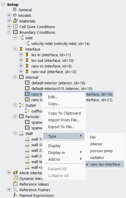
Select an appropriate interior interface and designate it as the RANS-LES interface, by right-clicking the boundary zone name in the tree (under Setup/Boundary Conditions) and selecting rans-les-interface in the Type sub-menu.
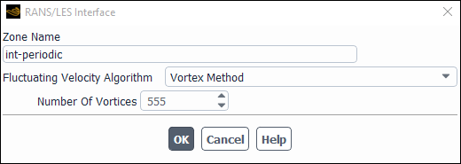
The RANS/LES Interface dialog box (Figure 15.30: The RANS/LES Interface Dialog Box) will open, allowing you to assign a Zone Name, as well as the Fluctuating Velocity Algorithm and the Number Of Vortices. The options for the Fluctuating Velocity Algorithm are:
No Perturbations
Spectral Synthesizer
Vortex Method
For more information about these options, refer to Inlet Boundary Conditions for Scale Resolving Simulations in the Theory Guide.
Note that the Number Of Vortices is the amount of vortices that the selected method distributes randomly over the face zone and uses to generate turbulent fluctuations. The value should be large enough to make sure there are no spots on the face zone that are unaffected by any vortex. Large numbers may slightly increase the CPU effort, but will not impair the results.
Note: The minimum advised number of vortices is approximately a quarter of the number of cell faces at the LES side of the interface.
If the RANS/LES interface is a non-conformal mesh interface, you can find the name of the interface interior zone that you want to change into a rans-les-interface zone by using the button in the Mesh Interfaces Dialog Box.
Important: It is recommended that the RANS-LES interface be situated in a region where there is no backflow.