


Acts as a Scoping Method for Remote Boundary Conditions.
 |
Object Properties
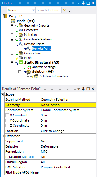
The Details Pane for this object includes the following properties.
| Category | Properties/Options/Descriptions | |
|---|---|---|
|
Scope |
Scoping Method: Options include Geometry Selection (default), Named Selection, Remote Point, Remote Points and Nodes, or . Free Standing Remote Points can be used to model structures such as Tuned Mass Dampers by directly connecting pieces of your model together. Note: When you specify , the Geometry, Pinball Region, Behavior, and DOF Selection properties do not appear in the Details view.
Geometry: Displays when the Scoping Method property is set to Geometry Selection. Select your geometric entity or mesh entity and then click the button. This option supports face, edge, vertex, node, or element face selection. Named Selection: Displays when the Scoping Method property is set to Named Selection. Choose a Named Selection from the drop-down menu. Named selections can be geometry-, element face-, or node-based. Outline Selection: Displays when the Scoping Method property is set to or . This property is scoped to an existing Remote Point. Select the entry field of this property, select the desired Remote Point objects from the Outline, and then select the Apply button that displays automatically. Once specified, this field displays the number of Remote Point objects you have selected (for example, , , etc.). Nodes: Displays when the Scoping Method property is set to . This option enables you to perform direct node scoping for the Remote Point in addition to the scoping of one or more Remote Point objects. This property behaves similar to the Geometry scoping method, enabling you to perform direct node-based scoping. Coordinate System: The Coordinate System based on the original location of the remote point. This property does not change if you modify the remote point’s position with the Location property. Note: When you scope a Remote Point to a load or a result (Scoping Method property is set to ), the direction used to calculate the load or to evaluate the result is based on the Coordinate System property of the Remote Point object. This also applies to when Remote Points like this are used with a Commands (APDL) object. X Coordinate: The distance from the coordinate system origin on the x axis. Y Coordinate: The distance from the coordinate system origin on the y axis. Z Coordinate: The distance from the coordinate system origin on the z axis. Location: When selected, this property displays the remote point's location. The property allows you to manually modify the remote point's original position. Changing the Location does not establish a new coordinate system (reflected by the above Coordinate System property) and re-plots the x, y, and z coordinate locations.
Important: When you first scope a Remote Point and you do not also define the Location property, the application sets the position of the remote point to the centroid of the scoped geometry selection(s) or if scoped to multiple Remote Points, the centroid of those Remote Points. Any subsequent scoping changes will not change this position. You must update the Remote Point's location as needed.
| |
|
Definition |
DOF Selection: Specify as Program Controlled (default) or Manual. Provides control of which DOF's will activate for corresponding constraint equations. If the Manual setting is selected, the following additional properties display.
Pilot Node APDL Name: Optional property that enables you to create a Mechanical APDL parameter (in the input file) and assign its value to the pilot node number of the Remote Point. This facilitates easy programmatic identification of the Remote Point’s pilot node for later use/reference in a Command object. | |
|
Advanced Visible for Behavior set to only. |
Material: Available when the Behavior property is set to . Select a material to define material properties for the beams used in the connection. Density is excluded from the material definition. Radius: Available when the Behavior property is set to . Specify a radius to define the cross section dimension of the circular beam used for the connection. |
Tree Dependencies
Valid Parent Tree Object: Remote Points.
Insertion Methods
Use any of the following methods after highlighting Model or Remote Points object:
Choose the option on the Model or Remote Points Context tabs.
Right-click the Model object or the Remote Points object or in the Geometry window and select > .
Right-click Options
In addition to common right-click options, relevant right-click options for this object include:
API Reference
See the Remote Point section of the ACT API Reference Guide for specific scripting information.
Additional Related Information
See the following sections for more information: