


The Construction Line feature is a unique geometry sketching tool you use to create line segments on or around your model that you eventually convert into line bodies. This section describes the methods and options used to sketch and produce these line bodies.
Defining a Construction Line
Select the option from the Construction Geometry drop-down menu on the Model Context tab. Once you have inserted the object, several additional options are available to insert additional objects. See the object reference section for the other methods.
Note: Using the Image Plane from File option of the Insert group on the Home tab, you can import an image into Mechanical and place it on or around your model based the on XY-plane of the selected coordinate system. You then use this image to very accurately sketch line segments. To properly trace over an imported image, you need to position your model using the same orientation that was used to capture the image, otherwise, your new sketch may be in an incorrect position compared to the model.
Once inserted, the object has the following Details pane categories and properties:
| Category | Property/Description |
|---|---|
|
Sketch Selection |
Method: Options for this property include: |
|
Active Sketch Details |
Sketch ID: This read-only property shows an application defined ID of the active sketch. You can use this ID for Construction Line ACT APIs. Association Type: This read-only property shows the entity type for the active sketch. Options include Geometric and Coordinate System. Association ID: This read-only property shows the ID of the sketch’s object based on the setting of the Association Type property, either Geometric or Coordinate System. If set to Geometric, the ID is a geometric entity ID (See “GeoEntityById” in the ACT API Reference Guide). If set to Coordinate System, the ID is an object ID (the Coordinate System’s object in the Outline). Note: These ID values are compatible with the Mechanical ACT APIs. |
|
Image Plane Properties |
The properties of this category enable you to import and overlay an image on your model to accurately sketch line bodies on or around your model. Image File: Import an image that overlays on the XY-plane of the selected Coordinate System. Using this image overlay you can very accurately sketch one or more line segments. Note that to properly trace over an imported image, you need to position your model using the same orientation that was used to capture the image, otherwise, your new sketch may be in an incorrect position compared to the model. Coordinate System: Specify where to place your image based on a Coordinate System. Show Coordinate System: Show the selected Coordinate System triad on the model. Options include or (default). Width: Specify the physical width of your image. For the best results, it is recommended that the ratio of physical width to physical height matches the aspect ratio of your image. Height: Specify the physical height of your image. For the best results, it is recommended that the ratio of physical width to physical height matches the aspect ratio of your image. Translucency: Increasing the value makes your image more and more transparent which may help you sketch a more accurate line. Horizontal Flip: Reverse your image horizontally. Vertical Flip: Reverse your image vertically. |
For an individual Construction Line object, you can create as many line bodies as desired. You can switch back and forth between each of the above methods for each line body, or group of line bodies, you create. The Sketch Selection property simply defines the method to select the active plane for planar sketching. The option specified for this property has no effect on the final geometry that will be added to the model. See the Understanding the Tools topic below for descriptions of the various tools and options available for this feature.
Generating Line Bodies
Once you have completed sketching your line bodies, use the Construction Line object's context (right-click) menu option to generate line bodies. Use the Update Geometry option to incorporate any desired additions/changes.
Once you have created a Line Body, you need to specify a cross section and assign a material. Review the Cross Section and material assignment topics as well and the Body object reference section for descriptions of all of the associated geometry properties.
Understanding the Tools
This topic describes the features and tools of the Construction Line Context menu that are organized into the following groups:
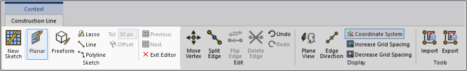
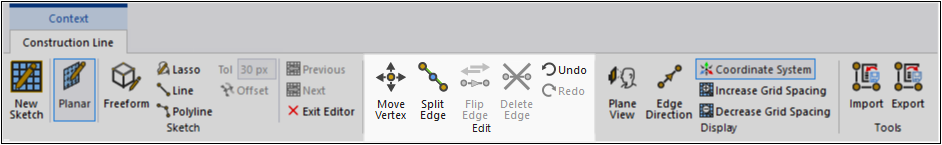
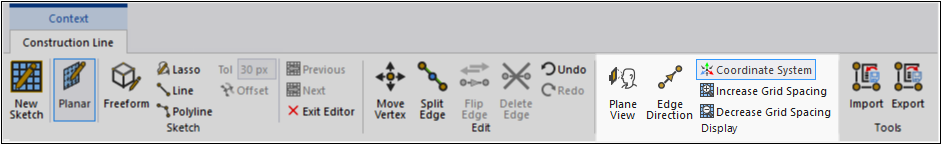
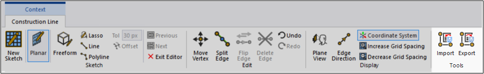
This is the default display of the Context tab for the Construction Line object.
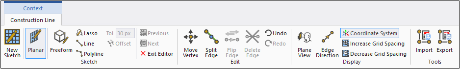
Sketch
The Sketch options group (highlighted below) contains draw tools that enable you to create line segments.
- New Sketch
This option is active by default when you insert the object. Select a desired plane on your model (based on a face selection) or you can set the Sketch Selection property to Coordinate System and select a user-defined coordinate system.
Available when the Sketch Selection Method property is set to , the New Sketch option specifies a new sketch plane on a face of your model that you select. Once specified, the Planar editor becomes active. Select a desired sketch option and create line segments.
- Planar
The Planar editor enables you to sketch 2D line segments on a given specified plane. Your line segments are bound to the specified geometry face or a Coordinate System, that is, your sketch can only be performed within this plane.
To begin sketching line segments, select the Lasso, Line or Polyline tool. You can also use the Offset tool.
- Freeform
The Freeform editor enables you to sketch 3D line segments between geometric entities (including face centroids) or the vertices of existing line segments. To begin sketching line segments, select the Line or Polyline tool.
- Lasso
The Lasso tool, only available for the 2D (Planar) editing mode, enables you to click and drag the mouse cursor to trace a line segment (beginning to end). This tool has an accompanying Tolerance (Tol) field that defines the number of pixels in between each vertex the tool automatically creates. Use the [Esc] key to complete a sketch.
- Line
The Line tool is available for both editing modes and enables you to make individual line segments. By default, when you create a line segment using this tool, point selections “snap” into place:
Using the Planar editor. This snapping takes precedence for sketch vertex points and to cursor placement. Holding the [Shift] key enables you to snap to a point on the plane grid.
On sketch vertices, edges, and face centroids using the Freeform editor. However, using Freeform, you can freely place points on faces without any snapping.
- Polyline
The Polyline tool is available for each editing mode and enables you to make a series of line segments that the application will use to generate a single line. The snapping capability is the same as it is for the Line tool. Use the [Esc] key to complete a sketch.
- Offset
The Offset option only becomes active when you 1) select one or more edges, and 2) select the Planar option. It enables you to create an offset of an edge(s), within the 2D sketching plane. When you activate the tool, drag and drop the edge(s) to a desired offset location. You can define multiple offsets. Note that you can also click a location on the plan where you would like the offset located.
- Previous/Next
The Previous and Next options cycle through the sketch planes you have created for the current Construction Line object.
- Exit Editor
The Exit Editor option deactivates all Construction Line Context tab options.
Tip: Note the following selection features:
Holding the [Shift] key enables grid point “snapping.” The application highlights a point on the grid to which you can connect your selection. This is helpful when placing and/or moving a vertex.
Box Selection: You can perform box selections by holding the [Shift] key and left mouse button and dragging right or dragging left.
Dragging Left: Select only segments that have both vertices in the box.
Dragging Right: Select segments with at least one vertex in the box.
For Planar mode, box-selection selects segments with both vertices lying in the sketching plane only.
Edit
The Edit group (highlighted below) contains tools for modifying or moving existing lines and edges.
- Move Vertex
When you select this option, you can highlight an existing vertex and move it via drag and drop. You can select multiple vertices using the [Ctrl] key. When you hold the [Shift] key and move a vertex, the application will snap it to the grid.
- Split Edge
The Split Edge option creates a new vertex on an existing line segment. You can use the [S] key to perform this action.
- Flip Edge
Active when a line is segment selected, this option enables you to invert the Edge Direction of the line segment. You can also use the [F] key to perform this action. Edge direction is the direction of the vector of the first point of your line segment to the second point. This direction can be displayed using the Edge Direction option.
- Delete Edge
Active when a line segment is selected, this option deletes the selected line segment. You can also use the [Delete] key.
Display
The options of the Display group are highlighted and described below.
- Plane View
Reorient the view of the active sketch plane to the XY-plane.
- Edge Direction
Display line segment edge direction. Edge direction is the direction of the vector of the first point of your segment to the second point.
- Coordinate System
Toggles the display of the triad for the active sketch's Coordinate System on and off.
- Increase/Decrease Grid Spacing
Increase or decrease the spacing of the grid display (by power of 10 based on the CAD unit).
Tip: You can use the key combinations [Ctrl]+[+] and [Ctrl]+[-] to increase and decrease the grid.
Tools
The Import options group (highlighted below) contains tools to import or export currently or previously defined line bodies.
- Import
Import previously exported line bodies in XML file format.
- Export
Export the currently defined line bodies in XML file format.