


You can use the Face Split feature to split a face into any number of faces. The face selected for the operation can come from either active or frozen bodies. It projects the selected edges or point pairs or split locations in a direction that is closest to target face.
Face Split Types: This property is used to define the type of face split. Four options are available in this property: "By Point and Edges," "By Location," “By Plane,” and “By Surface.” The default option is "By Point and Edges".
Target Face: This property facilitates the selection of the faces to be split. If the face split type is “By Point and Edges” or “By Location,” then only one face can be selected; otherwise, more than one face can be selected. The faces used in a Face Split Group as the target face cannot be in another Face Split group.
Tool Geometry: When the face split type is "By Point and Edges" you can select sketch point pairs, spot pairs, vertex pairs, sketch edges, 3D edges or different combinations of point pairs and edges. When the face split type is "By Location" you can create split locations on the target face and/or boundary edges of the target face by clicking on the graphics view. You can also select split locations which do not belong to the current Face Split Group but lie on the boundary edges of the target face of the current group.
When the face split type is “By Plane”, a plane can be selected as tool geometry. If the face split type is “By Surface”, a face (which is not selected in any other Face Split Group as the target face) can be selected.
Connect Locations: This property is applicable only when the face split type is "By Location". It has three options, "By Straight Line", "By Parametric Spline", and “By 3D Spline”. The default option is "By Straight Line". Vertices, 2D sketch points, and Spots can be selected by hit location, provided these points lie on the face being split. The “By 3D Spline” option uses a 3D curve from the selected points and splits the face straight across instead of following the parameterization of the faces as in the case of the “By Parametric Spline” option.
Merge Edges: This property is available only when the connect locations type is "By Straight Line." When the merge edges option is Yes it merges an allowable set of edges on the target face. The default option is Yes.
Select A Group: Clicking on the group header will highlight the corresponding target face.
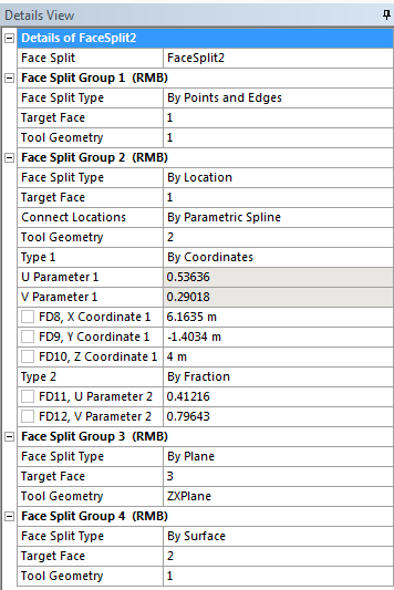
Type: This property is visible only when face split type is "By Location" and the number of tool geometries is more than one. This property defines two types of parameterization, "By Fraction" and "By Coordinates". The default option is "By Fraction".
Fraction/Parameter: When the property "Type" selected is "By Fraction", this property can be edited. This property defines the location of the split location.
X Coordinate, Y Coordinate, Z Coordinate: When the property "Type" selected is "By Coordinates", these properties can be edited. These properties define the location of the split in the global coordinate system.
Clicking a property of the split location in the Details View, the corresponding split location will be highlighted in the graphics view.
Face Split topics:
| Split Location Group Control via Context Menu |
| Graphics Context Menu Options |
| Errors/Warnings Status of Face Split Group |
GUI Navigation: to split a face
 |
Select the Sketching tab.
Use Rectangle from the Draw toolbox of the Sketching tab to draw a rectangle in the Graphics Window.
Click Extrude.
In the Details View, select the Depth property to enter a number greater than zero. Click Generate.
Create sketch/construction points, if needed, on the desired face to be split.
From the Tools Menu, select the Face Split feature.
The Target Face property is highlighted in the Details View. With the Single Select cursor, pick the face to be split.
Single click the yellow field in the Target Face field of the Details View.
Press Apply in the Details View.
The Target Face field in the Details View displays the number of faces. After selecting Target Face
Select the Tool Geometry property in the Details View.
Select sketch points, points, and vertices where you desire the face to be split.
After selecting sketch points and vertices.
Single click the yellow field in the Tool Geometry field of the Details View.
Press Apply in the Details View.
The Tool Geometry field in the Details View will display the number of line segments. Right-click in the Details View to Add New Face Split Group (Face Split Group 2).
Single click Face Split Type (of the new group) to activate the drop-down menu.
Select the down arrow to choose "By Location."
Repeat selection of the Target Face property to pick another face to be split.
Select Tool Geometry property in the Details View.
After selecting Target Face After creating split locations.
Click the selected face of the current group and/or edges of the face.
New Split Locations will be created at the click points. Press Apply.
Click Generate.
Edit the Face Split feature.
Select Face Split Group 1
a. Select any vertex or sketch point. It will add a new segment for Face Split Group 1. b. Right click on Graphics view. Select the option Remove Last Segment. It will remove the last segment created in Face Split Group 1. Now select the option Clear All Segments. It will remove all the remaining segments in Face Split Group 1. Select Face Split Group 2
a. Select any split location, and drag it over the face corresponding to Face Split Group 2 to a new desired location. Note that you can drag the Split Location when you are in "Tool Geometry " property. Make sure the point selection filter is on. b. You can remove all split location from Details View context menu or from Graphics context menu. c. Select a split location and then right click. Select the option Delete Location. It will delete the selected split location. d. Select another split location and then right click. Select the option Insert Location>Before. It will create a new split location before the selected split location. You can choose the option Insert Location>After if you want to insert a new split location after the selected Split Location.
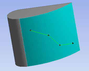
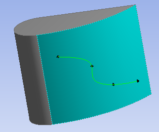
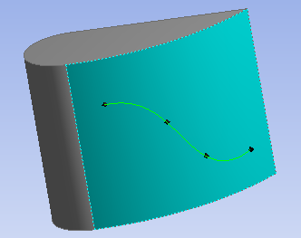
Example 35: Splitting a Highly Curved Face
If the face to be split is highly curved as shown below, you may not get expected results if you select very few points. Including interior locations will produce the desired result in such cases.
 Result with few points selected |  Result with inclusion of interior points |
Other Advanced Tools: