


The feature is a tool used to enclose the bodies of a model so that the material enclosing the bodies can be assigned to something such as a gas or fluid in the Mechanical application. The feature takes either all the bodies or selected bodies of the model as input, creates a frozen enclosure body around those bodies, and then cuts the bodies out of the enclosure. The frozen enclosure body will have a Fluid/Solid Property (as seen in the Details View when this body is selected) set to Fluid. This operation will not delete any bodies currently in the model. All types of bodies will be enclosed but only Solid bodies will be cut out of the enclosure. See Fluid/Solid Property for more information about editing the property.
Note: When working with surface bodies, their faces will not be cut from the enclosure body because it would violate the rules of Manifold Geometry. Therefore, no shared topology will be generated between surface bodies and their enclosures upon application of the Share Topology feature or transfer of the model into the Mechanical application.
The Enclosure feature supports symmetry models when the shape of enclosures is a box or a cylinder. A symmetry model may contain up to three symmetry planes. You can choose either full or partial models to be included in the enclosure. If a full model is used, symmetry planes will slice off the Enclosure feature and only a portion of the enclosure will be retained.

During the model transfer from Ansys DesignModeler to the Mechanical application, the Enclosure feature with symmetry planes forms two types of named selections if the Export Enclosure property is set toYes:
Open Domain: All exterior enclosure surfaces that are not coincident to any symmetry planes are grouped in an Open Domain named selection.
Symmetry Plane: For each symmetry plane, all faces, from both the enclosure and the model, that are coincident to the symmetry plane are grouped into a named selection.
Additionally, if the Export Enclosure property is set to Yes, each symmetry plane chosen in the Enclosure feature will be transferred to the Mechanical application as a coordinate system.
It is recommended that you do not change the symmetry plane selection after a model has been transferred to the Mechanical application. The Mechanical application will not delete the previous symmetry planes during updating. A similar note applies when using the Named Selection feature.
These additional properties allow you to control the behavior of the feature:
Shape: This property specifies the shape of the enclosure. There are four different shapes available:
Box (default) Sphere Cylinder User Defined User Defined Body: If User Defined is selected for the Shape property, then this property becomes available. It is an Apply/Cancel property that facilitates selection of the user defined enclosure body. The body selected for this property may not be included in the list of target bodies. Additionally, only one user-defined body can be selected.
Cylinder Alignment: If cylinder is selected for the Shape property then this property becomes available. This specifies the cylinder axis of the bounding cylinder surrounding the target bodies. There are four different alignments the cylinder can have:
Automatic (default) X-Axis Y-Axis Z-Axis Automatic alignment will align the cylinder axis in the largest direction (X, Y, or Z) of the bounding box surrounding the target bodies.
For the enclosure with symmetry planes, the following rules are applied for automatic alignment:
For one symmetry plane, the largest dimension of the bounding box for the target bodies is used.
For two symmetry planes, the intersection of the two symmetry planes is used.
For three symmetry planes, the intersection of the first two symmetry planes is used.
Number of Planes: This property defines how many symmetry planes are used in the enclosure. The default value is 0.
Symmetry Plane 1 : first symmetry plane selection
Symmetry Plane 2: second symmetry plane selection
Symmetry Plane 3: third symmetry plane selection
Model Type: This property specify either Full Model or Partial Model as input for the enclosure with symmetry planes:
Full Model: Ansys DesignModeler will use the chosen symmetry planes to cut the full model, leaving only the symmetrical portion. For each symmetry plane, material on the positive side of the plane (that is, the +Z direction) is kept, while material on the negative side is cut away. Partial Model: Since the model has already been reduced to its symmetrical portion, DesignModeler will automatically determine on which side of the symmetry planes the material lies.
Cushion: The cushion property specifies the distance between the model and the outside of the enclosure body. The enclosure is initially calculated to be just big enough to fit the model, and then the cushion value is applied to make the enclosure larger. The cushion is set to a default value and must be greater than zero.
Cushion values for Box or Cylinder type enclosures can be either Uniform or Non-Uniform. Non-Uniform type accepts different values for X, Y and Z directions for the Box dimension. Similarly Cylinder Enclosure takes the cushion values for radius, positive and negative reference directions.
This property is available for all enclosure shapes except User Defined. This property may also be set as a design parameter.
The bounding box calculation for the model used in the Enclosure feature is guaranteed to contain the model (or selected bodies). While the computed bounding box is usually very close to the minimum-bounding box, it is not guaranteed.
Target Bodies: This property specifies whether all of the bodies or only selected bodies of the model will be enclosed. The default is All Bodies.
Bodies: If Target Bodies is set to Selected Bodies then this property becomes available. It is an Apply/Cancel button property that facilitates selection of the target bodies that you wish to be enclosed. None of the bodies selected for this property can also be selected as the user-defined body.
Merge Parts: This property specifies whether or not the enclosure and its target bodies will be merged together to form a part. It is only available during feature creation or while performing Edit Selections. If Yes, the enclosure body (or bodies) and all target bodies will be merged into a single part. Only Solid bodies are considered when merging parts - line and Surface bodies will not be merged. If the property is set to no, then no attempt is made to group the bodies into the same part, nor is any attempt made to undo any groupings previously performed. The Merge Parts property is set to no by default, and will automatically be set to no after each Merge Parts operation.
Export Enclosure: Determines whether the open domain and symmetry plane data is transferred downstream to Mechanical. The default id Yes.
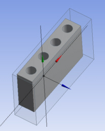
Shown below is the creation of each enclosure shape:
Box Enclosure of heat sink model.
Sphere Enclosure
Cylinder Enclosure with Y-Axis alignment
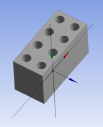
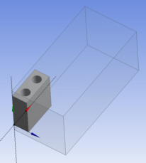
Shown below is the creation process of a User Defined Enclosure:
First Freeze the body or bodies that you will build your enclosure around.
Then create the User Defined Enclosure over the selected bodies.
Other Advanced Tools: