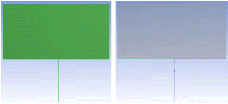
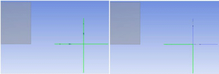
The feature is a tool used to create joints between different geometries of different bodies together so that their contact regions will be treated as shared topology when meshed in the Mechanical application. The feature takes two or more geometries (at least one should belong to a Surface body) as input. Selected geometry will be imprinted on each other as per requirement. There is no restriction on the states of the bodies you select; both active and frozen body selections are permitted. The Share Topology property allows you to control the behavior of the feature:
Share Topology: To treat the imprinted edges as shared topology in the Mechanical application, set the Shared Topology option to Yes. Imprinted edges will display an edge joint where the coincident edges are to signify that their edges will be shared. That is, two coincident edges will still exist in Ansys DesignModeler as separate edges, but when the model is attached to the Mechanical application, the edges are merged into one. If Share Topology is set to No, then edges will be imprinted on both surface bodies, but no shared topology information is kept. The default setting is Yes. See the Shared Topology section for more information.
Two more properties list the results of the Joint operation:
Edge joints generated: This tells you the number of edge joints that the Joint feature created. The value of this property will always be zero if Share Topology is set to No.
Expired edge joints: This will inform you of any edge joints that have expired due to model changes. If any edges in an edge joint are modified in any way, then the edge joint will become expired and no longer appear when viewing the edge joints. For this reason, it is recommended that you apply Joint features after you are done building your model. This property is not displayed if there are no expired edge joints for a Joint feature.
For example, suppose you wish to join the following two Surface bodies. Ansys DesignModeler would normally not allow these two bodies to be merged, since they created non-manifold geometry. Using the Joint feature, you can imprint the bodies and form shared topology between them.
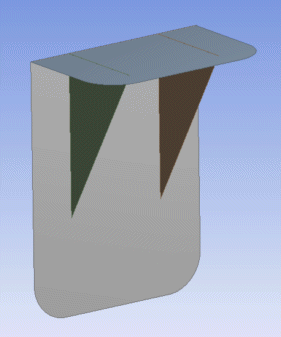
After generating the feature, edges are imprinted onto all three bodies, and topology sharing information is created. Notice that the shared edges are shown as thick blue lines. Additionally, the three bodies are grouped under the same part, and the share topology method for the part and bodies are set to Edge Joints.
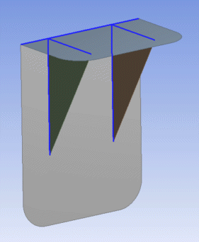
The Joint feature limits selection to the required geometries from the bodies rather than the selection of a sheet or line body as a whole. Illustrated below is an example of such selection and the resulting Edge Joint.
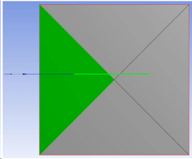
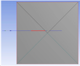
For more information on viewing edge joints, see Show Edge Joints.
Joint Limitations
Usage with line bodies — The Joint feature cannot be used to create an edge joint between two line bodies or imprint lines on one another.
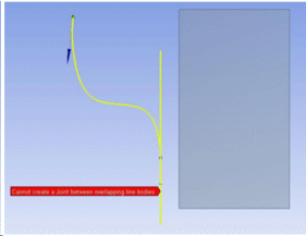
Overlapping line bodies — The Joint feature cannot be used to create a joint when the line bodies overlap or touch one another on a Surface body.
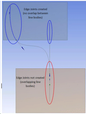
The Joint feature will not create joints between geometries of the same body. The selection in the following figure for a Joint feature is invalid as both the faces are from the same sheet body.
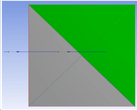
Even if the joint feature is partially successful, it may split the edges in selected geometries.
In the following figure (I), one face of the sheet body and one edge of a line body were given as the input of the Joint Feature. In this case the Joint Feature will be partially successful and results in splitting of the edge of the face at the intersection.
In the following case, two edges of different wire bodies were given as the input for the Joint Feature. In this case, the Joint Feature will be partially successful and will imprint both the edges on each other and thereby splitting the edges at the point of intersection as shown in the figure (II).
Other Advanced Tools:


