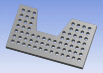
The Pattern feature allows you to create copies of faces and bodies in three patterns:
Linear: a direction and offset distance is required.
Rectangular: two sets of directions and offsets are needed.
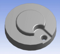
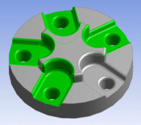
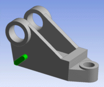
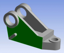
For face selections, each connected face set is patterned independently of other face sets. For a face pattern to succeed, the copied instance of the face set must remain coincident with the body it originated from, or be able to be easily extended to it. The new faces of the pattern must touch the topological entities that were incident to the original face set, also known as the base region. Additionally, the instances for face sets may not intersect each other or the original face set. The faces may belong to either active or frozen bodies. An example of the base region is shown below.
Example 66: Base Region
All instances of the pattern faces selected in the picture on the left must lie in the base region highlighted in the picture on the right. Note that this means the instances may not intersect the hole where the original pattern faces reside.
 |  |
There are no such restrictions for selected bodies. Solid, Surface, and line bodies are all acceptable. If the selected bodies are active, then the patterned copies will be added to the model as active bodies and merged with other active bodies. For selected bodies that are frozen, their instances will be added to the model as frozen bodies.
The properties of the feature are:
Pattern Type: Defines either a Linear, Circular, or Rectangular pattern. The default setting is Linear.
Geometry: An Apply/Cancel button property that accepts face and body selections.
Direction: The direction for a Linear pattern, or the first of two directions for a Rectangular pattern.
Offset: The offset distance for a Linear pattern, or the first of two offsets for a Rectangular pattern. This is the distance between each instance of the pattern. Its value must be non-zero.
Axis: The rotation axis for a Circular pattern. The axis can be a Direction Reference selected from a plane, 2D sketch edge, 3D model edge, face or two points.
Angle: The rotation angle for a Circular pattern. This is the angle between each instance of the pattern. If the value of this property is 0°, then Ansys DesignModeler will automatically calculate the angle necessary to evenly space the patterns about the rotation axis, and you will see "Evenly Spaced" indicated in the property instead of a numerical value. The default value for Angle is 0°.
Copies: The number of copies to create for Linear and Circular patterns. For Rectangular patterns this is the number of copies to create in the first direction. The value must be greater than or equal to zero. The default value is 1.
Direction 2: The second of two directions for a Rectangular pattern.
Offset 2: The second of two offset distances for a Rectangular pattern. This is the distance between each instance of the pattern in the second direction. Its value must be non-zero.
Copies 2: The number of copies to create in the second direction for Rectangular patterns. The value must be greater than or equal to zero. The default value is 1.
Patterning Line Bodies
When patterning line bodies, each patterned edge will inherit the alignment from its source edge. For patterns that involve rotation, the bodies will rotate, but their alignments will not. The derived edge will attempt to use the same alignment object as its source edge. You may need to adjust edge alignments to orient patterned line bodies as desired.
Patterning a Multibody Part
When patterning bodies of a multibody part, if a new part is created (usually only for the first time) the share topology method of the new part is set to be the same as the share topology method of the original source part.
Other Advanced Tools:


