There are several ways in which you can modify or manipulate the mesh after it has been read into Ansys Fluent. You can scale, translate, or rotate the mesh / zones, copy, merge, or separate zones, create or decouple periodic zones, fuse boundaries, and smooth and swap faces. Methods for partitioning meshes to be used in a parallel solver are discussed in Mesh Partitioning and Load Balancing.
Important: Whenever you modify the mesh, you should be sure to save a new case file (and a data file, if data exists). If you have old data files that you would like to be able to read in again, be sure to retain the original case file as well, as the data in the old data files may not correspond to the new case file.
Information about mesh manipulation is provided in the following sections:
- 6.12.1. Merging Zones
- 6.12.2. Separating Zones
- 6.12.3. Fusing Face Zones
- 6.12.4. Creating Periodic Zones and Interfaces
- 6.12.5. Decoupling Periodic Zones
- 6.12.6. Slitting Face Zones
- 6.12.7. Orienting Face Zones
- 6.12.8. Extruding Face Zones
- 6.12.9. Replacing, Deleting, Deactivating, and Activating Zones
- 6.12.10. Copying Cell Zones
- 6.12.11. Replacing the Mesh
- 6.12.12. Managing Adjacent Zones
- 6.12.13. Reordering the Domain
- 6.12.14. Scaling the Mesh
- 6.12.15. Translating the Mesh
- 6.12.16. Rotating the Mesh
- 6.12.17. Improving the Mesh by Smoothing and Swapping
- 6.12.18. Boundary Layer Redistribution
- 6.12.19. Deleting Cells
To simplify the solution process, you may want to merge zones. Merging zones involves combining multiple zones of similar type into a single zone. Setting boundary conditions and postprocessing may be easier after you have merged similar zones.
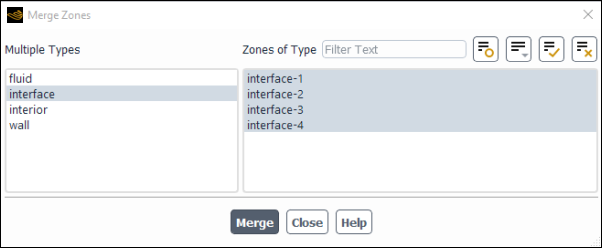
Zone merging is performed in the Merge Zones Dialog Box (Figure 6.90: The Merge Zones Dialog Box).
Domain → Zones
→ Combine → Merge...
Ansys Fluent allows you to merge zones of similar type into a single zone. This is not necessary unless the number of zones becomes prohibitive to efficient setup or postprocessing of the numerical analysis. For example, setting the same boundary condition parameters for a large number of zones can be time-consuming and may introduce inconsistencies. In addition, the postprocessing of the data often involves surfaces generated using the zones. A large number of zones often translates into a large number of surfaces that must be selected for the various display options, such as color contouring. Fortunately, surfaces can also be merged (see Grouping, Prioritizing, Editing, Renaming, and Deleting Surfaces), minimizing the negative impact of a large number of zones on postprocessing efficiency.
Although merging zones can be helpful, there may be cases where you will want to retain a larger number of zones. Since the merging process is not fully reversible, a larger number of zones provides more flexibility in imposing boundary conditions. Although a large number of zones can make selection of surfaces for display tedious, it can also provide more choices for rendering the mesh and the flow-field solution. For instance, it can be difficult to render an internal flow-field solution. If the outer domain is composed of several zones, the meshes of subsets of these zones can be plotted along with the solution to provide the relationship between the geometry and solution field. Merging zones may also adversely affect dynamic zones and mesh interfaces.
The procedure for merging multiple zones of the same type into a single zone is as follows:
Select the zone type in the Multiple Types list. This list contains all the zone types for which there are multiple zones. When you choose a type from this list, the corresponding zones will appear in the Zones of Type list.
Select two or more zones in the Zones of Type list.
Click the button to merge the selected zones. Note that if your case file has dynamic zones or mesh interfaces, the Warning dialog box will open before the merge is initiated, allowing you to specify whether you want to delete such zones or interfaces first (see Warning Dialog Box for details).
Important: Remember to save a new case file (and a data file, if data exists).
Upon reading a mesh file, Ansys Fluent automatically performs zone separations in two conditions. If a face zone is attached to multiple cells zones in the preprocessor, the face zone will be separated so that each one is attached to only one cell zone. Furthermore, if you have defined an internal face as a wall type, an additional shadow wall zone will be generated (for example, for a wall named baffle, a shadow wall zone named baffle-shadow will be generated).
There are several methods available in Ansys Fluent that allow you to manually separate a single face or cell zone into multiple zones of the same type. If your mesh contains a zone that you want to break up into smaller portions, you can make use of these features. For example, if you created a single wall zone when generating the mesh for a duct, but you want to specify different temperatures on specific portions of the wall, you will need to break that wall zone into two or more wall zones. If you plan to solve a problem using the sliding mesh model or multiple reference frames, but you forgot to create different fluid zones for the regions moving at different speeds, you will need to separate the fluid zone into two or more fluid zones.
Important:
After performing any of these separations, you should save a new case file. If data exists, it is automatically assigned to the proper zones when separation occurs, so you should also write a new data file. The old data cannot be read on top of the case file in which the zones have changed.
The maximum number of zones into which you can separate any one face zone or cell zone is 32.
There are four ways to separate face zones and two ways to separate cell zones. The face separation methods will be described first, followed by the cell separation tools. Decoupling of periodic zones is discussed in Decoupling Periodic Zones.
Note that all of the separation methods allow you to report the result of the separation before you commit to performing it.
For more information, see the following sections:
For geometries with sharp corners, it is often easy to separate face zones based on significant angle. Faces with normal vectors that differ by an angle greater than or equal to the specified significant angle will be placed in different zones. For example, if your mesh consists of a cube, and all 6 sides of the cube are in a single wall zone, you would specify a significant angle of 89°. Since the normal vector for each cube side differs by 90° from the normals of its adjacent sides, each of the 6 sides will be placed in a different wall zone.
If you have a small face zone and would like to put each face in the zone into its own zone, you can do so by separating the faces based on face. Each individual face (triangle, quad, or polygon) will be separated into different zones.
You can also separate face zones based on cell registers. For example, you can mark cells based on their location in the domain (region register), their boundary closeness (boundary register), field values of some variable, or any of the cell marking methods discussed in Using Cell Registers. When you specify which register is to be used for the separation of the face zone, all faces of cells that are marked will be placed into a new face zone.
Finally, you can separate face zones based on contiguous regions. For example, when you use coupled wall boundary conditions you need the faces on the zone to have a consistent orientation. Consistent orientation can only be guaranteed on contiguous regions, so you may need to separate face zones to allow proper boundary condition specification.
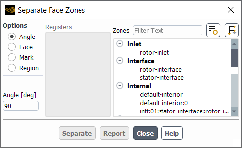
To break up a face zone based on angle, face, cell register mark, or region, use the Separate Face Zones Dialog Box (Figure 6.91: The Separate Face Zones Dialog Box).
Domain → Zones
→ Separate → Faces...
Important: If you are planning to separate face zones, you should do so before performing any adaptions using the hanging node adaption method. Face zones that contain hanging nodes cannot be separated.
The steps for separating faces are as follows:
Select the separation method (Angle, Face, Mark, or Region) under Options.
Specify the face zone to be separated in the Zones list.
If you are separating by face or region, skip to the next step. Otherwise, do one of the following:
If you are separating faces by angle, specify the significant angle in the Angle field.
If you are separating faces by mark, select the cell register to be used in the Registers list.
(optional) To check what the result of the separation will be before you actually separate the face zone, click the button. The report will look like the following example:
 45 faces in contiguous region 0
 30 faces in contiguous region 1
 11 faces in contiguous region 2
 14 faces in contiguous region 3
 Separates zone 4 into 4 zone(s).
To separate the face zone, click the button. A report will be printed in the console like the following example:
 45 faces in contiguous region 0
 30 faces in contiguous region 1
 11 faces in contiguous region 2
 14 faces in contiguous region 3
 Separates zone 4 into 4 zone(s).
 Updating new zone information ...
    created new zone wall-4:001 from wall-4
    created new zone wall-4:002 from wall-4
    created new zone wall-4:010 from wall-4
 done.
Important: When you separate the face zone by cell register mark, you may sometimes find that a face of a corner cell will be placed in the wrong face zone. You can usually correct this problem by performing an additional separation, based on angle, to move the offending face to a new zone. You can then merge this new zone with the zone in which you want the face to be placed, as described in Merging Zones.
For more information, see the following sections:
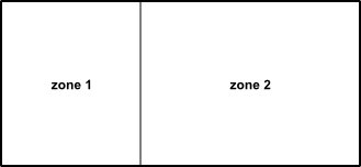
If you have two or more enclosed cell regions sharing internal boundaries (as shown in Figure 6.92: Cell Zone Separation Based on Region), but all of the cells are contained in a single cell zone, you can separate the cells into distinct zones using the separation-by-region method. Note that if the shared internal boundary is of type interior, you must change it to another double-sided face zone type (fan, radiator, and so on) prior to performing the separation.
You can also separate cell zones based on the marks stored in cell registers. You can mark cells using any of the methods discussed in Using Cell Registers (for example, you can mark cells with a certain field value range or cells inside or outside a specified region). When you specify which register is to be used for the separation of the cell zone, cells that are marked will be placed into a new cell zone.
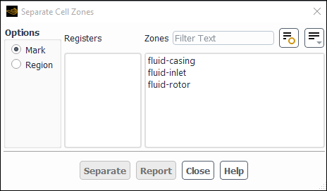
To break up a cell zone based on region or cell register mark, use the Separate Cell Zones Dialog Box (Figure 6.93: The Separate Cell Zones Dialog Box).
Domain → Zones
→ Separate → Cells...
Important: If you are planning to separate cell zones, you should do so before performing any adaptions using the hanging node adaption method. Cell zones that contain hanging nodes cannot be separated.
The steps for separating cells are as follows:
Select the separation method (Mark or Region) under Options.
Specify the cell zone to be separated in the Zones list.
If you are separating cells by mark, select the cell register to be used in the Registers list.
(optional) To check what the result of the separation will be before you actually separate the cell zone, click the button. The report will look like this:
Separates zone 14 into two zones, with 1275 and 32 cells.
To separate the cell zone, click the button. Ansys Fluent will print the following information:
 Separates zone 14 into two zones, with 1275 and 32 cells.
 No faces marked on thread, 2
 No faces marked on thread, 3
 No faces marked on thread, 1
 No faces marked on thread, 5
 No faces marked on thread, 7
 No faces marked on thread, 8
 No faces marked on thread, 9
 No faces marked on thread, 61
 Separates zone 62 into two zones, with 1763 and 58 faces.
 All faces marked on thread, 4
 No faces marked on thread, 66
 Moved 32 cells from cell zone 14 to zone 10
 Updating new zone information ...
    created new zone interior-4:010 from interior-4
    created new zone interior-6:009 from interior-6
    created new zone fluid-14:008 from fluid-14
 done.
As shown in the example above, separation of a cell zone will often result in the separation of face zones as well. When you separate by mark, faces of cells that are moved to a new zone will be placed in a new face zone. When you separate by region, faces of cells that are moved to a new zone will not necessarily be placed in a new face zone.
If you find that any faces are placed incorrectly, see the comment above, at the end of the inputs for face zone separation.
The face-fusing utility is a convenient feature that can be used to fuse boundaries (and merge duplicate nodes and faces) created by assembling multiple mesh regions. When the domain is divided into subdomains and the mesh is generated separately for each subdomain, you will combine the subdomains into a single file before reading the mesh into Fluent. For details, see Reading Multiple Mesh/Case/Data Files. This situation could arise if you generate each block of a multiblock mesh separately and save it to a separate mesh file. Another possible scenario is that you decided, during mesh generation, to save the mesh for each part of a complicated geometry as a separate part file. (Note that the mesh node locations need not be identical at the boundaries where two subdomains meet; see Non-Conformal Meshes for details.)
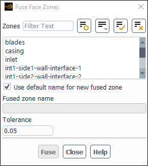
The Fuse Face Zones dialog box (Figure 6.94: The Fuse Face Zones Dialog Box) allows you to merge the duplicate nodes and delete these artificial internal boundaries.
Domain → Zones
→ Combine → Fuse...
The boundaries on which the duplicate nodes lie are assigned zone ID numbers (just like
any other boundary) when the mesh files are combined, as described in Reading Multiple Mesh/Case/Data Files. You need to keep track of the zone ID numbers
when tmerge or the meshing mode of Fluent reports its
progress or, after the complete mesh is read in, display all boundary mesh zones and use the
mouse-probe button to determine the zone names (see Controlling the Mouse Button Functions for information about the mouse button functions).
Alternatively, you can specify a name for the fused zone.
Note: For adapted meshes, fusing of face zones is only possible in serial with the PUMA adaption method (which is the default method for 3D).
The steps for fusing face zones are as follows:
Select the zones to be fused in the Zones list.
Important: When using the Fuse Face Zone utility, each of the selected face zones must be fused in its entirety with another face zone having the same connectivity. Partial fusing of face zones is not supported.
(Optional) If you would like to specify a name for the fused zone rather than use an automatically generated name (for instance, to preserve the original name of one of the face zones), disable Use default name for new fused zone and enter the desired name.
Click the button to fuse the selected zones.
If all of the appropriate faces do not get fused using the default Tolerance, you should increase it and attempt to fuse the zones again. (This tolerance is the same as the matching tolerance discussed in Creating Periodic Zones and Interfaces.) The Tolerance should not exceed 0.5, or you may fuse the wrong nodes.
You can also fuse zones using the
mesh/modify-zones/fuse-face-zones text command, as shown in the
following example.
/mesh/modify-zones >fuse-face-zones() Zone to fuse(1) [()]w1.topZone to fuse(2) [()]w3Zone to fuse(3) [()][Enter]Choose from list (automatic w3 w1.top) or pick your own Enter the fused zone name: [automatic]w3Name of zone 14 is changed into w3. Fused list of zones successfully.
Important: Remember to save a new case file (and a data file, if data exists) after fusing faces.
Meshes imported from structured mesh generators or solvers (such as FLUENT 4) can often be O-type or C-type meshes with a reentrant branch cut where coincident duplicate nodes lie on a periodic boundary. Since Ansys Fluent uses an unstructured mesh representation, there is no reason to retain this artificial internal boundary. (You can preserve these periodic boundaries and the solution algorithm will solve the problem with periodic boundary conditions.)
To fuse this periodic zone with itself, you must first decouple the periodic zone, as described in Decoupling Periodic Zones. This will create two symmetry zones that you can fuse using the procedure above.
Note that if you need to fuse portions of a non-periodic zone with itself, you must
use the mesh/modify-zones/fuse-face-zones text command.
mesh →
modify-zones →
fuse-face-zones
This command will prompt you for the name or ID of each zone to be fused. (You will
enter the same zone twice.) To change the node tolerance, use the
mesh/modify-zones/matching-tolerance text command.
Ansys Fluent allows you to assign periodicity to your mesh by coupling a pair of face zones. If the two zones are conformal (that is, have identical node and face distributions), then you can change them to be a pair of coupled zones that are both of type periodic. If the two zones are not identical at the boundaries within a specified tolerance, then you can change them both to be of type interface and include them in a non-conformal mesh interface that is periodic.
Important: Remember to save a new case file (and a data file, if data exists) after creating or decoupling a periodic boundary pair.
To create a periodic boundary zone pair or interface, perform the following steps:
Select the two boundary zones that make up the periodic pair in the Outline View (under Setup/Boundary Conditions). Note that you can select multiple zones by holding the Ctrl key while selecting. The zones cannot be of type interior or periodic. The order of selection will not affect the calculation results, though it may affect the naming: for conformal pairings, the first zone you select is considered the primary zone of the pair and will be renamed according to your specifications (while the second zone you select is considered the shadow zone).
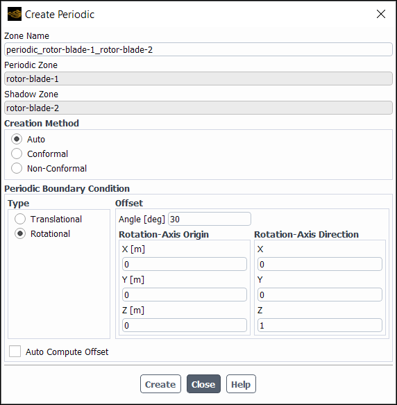
Right-click one of the selected zones and select Periodic... from the menu that opens, in order to open the Create Periodic dialog box.
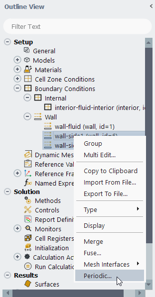
Perform the following steps in the Create Periodic dialog box.
Enter a Zone Name. For conformal pairings, the first boundary zone you selected in step 1. is considered the primary zone and will be renamed with this Zone Name during the creation process; for non-conformal pairings, this Zone Name will be used for both the resulting mesh interface and a single periodic boundary zone.
Make a selection from the Creation Method list to indicate whether the face zones that make up the periodic pair are Conformal or Non-Conformal. If you are unsure, you can select Auto and Fluent will automatically handle this decision (in which case a conformal pairing will be used if possible).
Note: For pairings that are non-conformal, the resulting periodic mesh interface will use the Matching option by default. For details about the Matching option, see Matching Option.
Define the settings in the Periodic Boundary Condition group box:
Select either Translational or Rotational from the Type list to define the type of periodicity for the pairing.
Retain the enabled default setting of Auto Compute Offset if you want Ansys Fluent to automatically compute the translational offset or the angle of the rotational offset. Otherwise, you can disable the Auto Compute Offset option and manually enter values to define the offset.
Important: When using auto computation for 3D cases, you should ensure that the mesh resolution on the periodic interface zone pairs are similar if both of the following conditions are met: the periodic interface zone pairs are not planar; and they are not connected by at least two face zones that meet at an edge that points from one periodic zone to the other. In such situations, having a similar mesh resolution will produce more precise offset calculations (and subsequently, more accurate solutions). It is recommended that the average mesh size on one boundary should not be more than twice that of the other.
For rotationally periodic pairings, enter values for the Rotation-Axis Origin and the Rotation-Axis Direction. Note that auto computation of the offset does not mean that these fields are also detected automatically and updated.
Click to create the periodic pairing. If it is a conformal pairing, the face zones are both changed to be of type periodic; the primary zone is renamed according to your specified Zone Name, and the shadow zone will retain its original name or (if it uses a default name) will be renamed automatically to reflect the new type (as described in Changing Cell and Boundary Zone Types). If it is a non-conformal pairing, both face zones are changed to be of type interface, and a face zone of type periodic and a mesh interface is created.
When attempting to create a conformal periodic boundary zone pair, Fluent will check to see if the faces on the selected zones “match” (that is, whether or not the nodes on corresponding faces are coincident). The matching tolerance for a face is a fraction of the minimum edge length of the face. If the creation of a conformal periodic boundary zone pair fails, you can change the matching tolerance using the following text command. The tolerance should not exceed 0.5, or you may match up the periodic zones incorrectly and corrupt the mesh.
mesh→modify-zones→matching-toleranceWhen using the density-based solver, you can specify a pressure jump for a conformal periodic zone pair; for details, see Periodic Flows.
Note that the functionality of the Create Periodic dialog box can
also be accessed through the
define/boundary-conditions/modify-zones/create-periodic-interface
text command.
For more information about non-conformal periodic boundaries and an alternate way to create them, see Non-Conformal Meshes and Using a Non-Conformal Mesh in Ansys Fluent, respectively.
If you want to decouple the zones in a periodic pair (also referred to as "deleting" or "slitting" a periodic pair), right-click the periodic zone in the Outline View (under Setup/Boundary Conditions/Periodic), and select Delete in the menu that opens. For conformal pairings, both of the zones in the periodic pair are changed to be of type symmetry; for non-conformal pairings, the original face zones remain as type interface and the associated mesh interface and periodic zone are deleted.
The face-zone slitting feature has two uses:
You can slit a single boundary zone of any double-sided type (that is, any boundary zone that has cells on both sides of it) into two distinct zones.
You can slit a coupled wall zone into two distinct, uncoupled wall zones.
When you slit a face zone, Fluent will duplicate all faces and nodes, except those nodes that are located at the ends (2D) or edges (3D) of the zone. One set of nodes and faces will belong to one of the resulting boundary zones and the other set will belong to the other zone. The only ill effect of the shared nodes at each end is that you may see some inaccuracies at those points when you graphically display solution data with a slit boundary. (Note that if you adapt the boundary after slitting, you will not be able to fuse the boundaries back together again.)
Before you can slit, you first need to select the zone in the Boundary
Condition task page and change the Type to
wall. Upon changing the Type to
wall, another shadow zone will be created (that is, if the original
zone is called rad-outlet, another zone called
rad-outlet-shadow will be created). Then you can apply the
mesh/modify-zones/slit-face-zone text command on either of the
walls (that is, rad-outlet or rad-outlet-shadow)
to separate them into two distinct walls.
Important: When a wall and wall-shadow pair is created by slitting a face zone, the wall will inherit the zone id number and face orientation of the original zone. A new zone id number will be created and assigned to the wall-shadow.
For example, the outlet of the radiator in an underhood application is typically of
interior type (that is, has cells on both sides). If you know the
mass flow rate through this zone (either from other CFD models or from test data) and want
to apply it as a boundary condition at the radiator outlet, you first need to slit the
radiator outlet. To be able to slit it, select wall from the
Type drop-down list in the Boundary Conditions
task page for this outlet. It will create a wall and a shadow. Then you can use the TUI
command (mesh/modify-zones/slit-face-zone) to slit them. After it
is slit, two additional walls will be created, one facing one side of the outlet and another
facing the other. Then you can select the appropriate wall and change the
Type to mass-flow-inlet and specify the mass
flow rate using the Mass-Flow Inlet Dialog Box. There is no option of
mass-flow-inlet without first slitting it.
Important: You should not confuse “slitting” a face zone with “separating” a face zone. When you slit a face zone, additional faces and nodes are created and placed in a new zone. When you separate a face zone, a new zone will be created, but no new faces or nodes are created; the existing faces and nodes are simply redistributed among the zones.
If you want to slit a face zone, you can use the
mesh/modify-zones/slit-face-zone text command.
mesh → modify-zones →
slit-face-zone
You will specify the face zone’s name or ID, and Fluent will replace the zone with two zones:
/mesh/modify-zones >slit-face-zoneFace zone id/name []wall-4zone 4 deleted face zone 4 created face zone 10 created
Important: Remember to save a new case file (and a data file, if data exists) after slitting faces.
The faces of a boundary face zone (which have cells only on one side) are oriented such that the normals are all pointing in one direction. However, for internal face zones (which have cells on both sides), the normals are allowed to point in either direction. To orient them so that they all point in one direction, you can use the following TUI command:
mesh → modify-zones →
orient-face-zone
Having all of the normals oriented in one direction is needed for some boundary condition types. For example, the fan boundary condition type determines the flow direction based on its normals. If some of the normals are pointing in one direction and some in the other, the correct flow orientation cannot be determined, which leads to incorrect results.
The ability to extrude a boundary face zone allows you to extend the solution domain without having to exit Fluent. A typical application of the extrusion capability is to extend the solution domain when recirculating flow is impinging on a flow outlet. The current extrusion capability creates prismatic or hexahedral layers based on the shape of the face and normal vectors computed by averaging the face normals to the face zone’s nodes. You can define the extrusion process by specifying a list of displacements (in SI units) or by specifying a total distance (in SI units) and parametric coordinates.
Important:
Note that extrusion is not possible from boundary face zones that have hanging nodes.
Extruding face zones is not allowed on polygonal face zones.
Extruding face zones is only allowed in the 3D version of Ansys Fluent.
You can specify the extrusion by entering a list of displacement distances (in SI
units) using the mesh/modify-zones/extrude-face-zone-delta text
command.
mesh → modify-zones →
extrude-face-zone-delta
Note: This text command is not available in the parallel version of Ansys Fluent.
You will be prompted for the boundary face zone ID or name and a list of displacement distances.
You can specify the extrusion by specifying a distance (in SI units) and parametric
coordinates using the mesh/modify-zones/extrude-face-zone-para
text command.
mesh → modify-zones →
extrude-face-zone-para
Note: This text command is not available in the parallel version of Ansys Fluent.
You will be prompted for the boundary face zone ID or name, a total distance, and a list of parametric coordinates. The list of parametric coordinates should begin with 0.0 and end with 1.0. For example, the following list of parametric coordinates would create two equally spaced extrusion layers: 0.0, 0.5, 1.0.
Ansys Fluent allows you to append or replace an existing cell zone in the mesh. You can also permanently delete a cell zone and all associated face zones, or temporarily deactivate and activate zones from your Ansys Fluent case.
This feature allows you to replace a small region of a computational domain with a new region of different mesh quality. This functionality will be required where you may want to make changes to the geometry or mesh quality for any part of the domain. This ability of Ansys Fluent will save you time, since you can modify only the required part of the domain without remeshing the whole domain every time.
The replacement mesh must be prepared in advance, with the following considerations:
The replacement mesh must contain a single cell zone.
The cell zone in the replacement mesh must be of the same zone type as the zone that is being replaced.
If the boundaries of the replacement mesh will form a non-conformal interface with existing zones (that is, zones that are not replaced in the existing mesh), these boundaries should be based on the same geometry as the existing zones. If there are sharp features (for example, 90-degree angles) or curvature in the mesh, it is especially important that both sides of the interface closely follow that feature.
The replacement cell zone does not need to have the same name as the existing zone being replaced.
When naming the boundary zones of the replacement cell zone, note that boundary conditions will be automatically transferred from the existing cell zone based on name. All boundaries of the replacement cell zone that have unique names will be assigned the default boundary condition for that zone type.
When selecting the file with the replacement cell zone, note that legacy mesh files (
.msh) and legacy case files (.cas) may be selected, but default CFF mesh files (.msh.h5) and CFF case files (.cas.h5) may not.
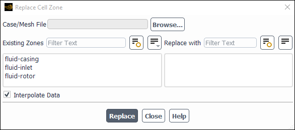
Replacing a zone is performed using the Replace Cell Zone Dialog Box (Figure 6.96: The Replace Cell Zone Dialog Box).
Domain → Zones
→ Replace Zone...
To replace a zone, do the following:
Click Browse... and select the new or modified mesh containing the cell zone that will replace one of the cell zones in the current mesh.
The name of the cell zone in the replacement mesh will be displayed in the Replace with list.
Under Existing Zones, select the zone you want to replace.
Under Replace with, select the zone from the replacement mesh.
Enable/Disable Interpolate Data, if data already exists. If the replacement cell zone is geometrically different, then Interpolate Data can be turned off to prevent data interpolation over the non-matching geometries.
Important: Disable Interpolate Data if the zone being replaced is part of an overset interface.
Click Replace to replace the selected zone.
Set up the boundary conditions for any of the boundaries of the replacement mesh that do not share a name with one of the existing boundaries.
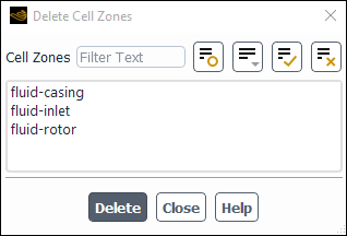
To permanently delete zones, select them in the Delete Cell Zones Dialog Box (Figure 6.97: The Delete Cell Zones Dialog Box), and click .
Domain → Zones
→ Delete...
All of the cells, faces, and nodes associated with the cell zone will be deleted. If one of the faces is of type interior and borders another cell zone, the face will automatically be changed to a wall and will stay attached to the remaining cell zone.
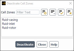
To deactivate zones, select them in the Deactivate Cell Zones Dialog Box (Figure 6.98: The Deactivate Cell Zones Dialog Box), and click Deactivate.
Domain → Zones
→ Deactivate...
Deactivation will separate all relevant interior face zones (that is, fan, interior, porous-jump, or radiator) into wall and wall-shadow pairs.
Note: When you deactivate a zone using the Deactivate Cell Zones dialog box, Ansys Fluent will remove the zone from the mesh and from all relevant solver loops.
Important: If a cell zone contains mesh interfaces it cannot be deactivated until the solution has been initialized.
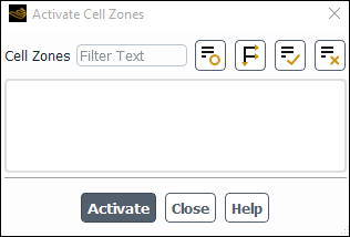
You can reactivate the zones and recover the last data available for them using the Activate Cell Zones Dialog Box (Figure 6.99: The Activate Cell Zones Dialog Box).
Domain → Zones
→ Activate...
Note: The Activate Cell Zones dialog box will only be populated with zones that were previously deactivated.
After reactivation, you need to make sure that the boundary conditions for the wall and wall-shadow pairs are restored correctly to what you assigned before deactivating the zones. If you plan to reactivate them at a later time, make sure that the face zones that are separated during deactivation are not modified. Adaption, however, is supported.
You can create a copy of a cell zone that is offset from the original either by a translational distance or a rotational angle. Note that in the copied zone, the bounding face zones are all converted to walls, any existing cell data is initialized to a constant value, and non-conformal interfaces and dynamic zones are not copied; otherwise, the model settings are the same as in the original zone.
To copy a zone, use the following text command:
mesh → modify-zones →
copy-move-cell-zone
You will then be prompted to enter the ID of the zone you want to copy, and either the distance for translation in each of the axes or the rotational angle, origin, and axis.
Note that if you want the copied zone to be connected to existing zones, you must either fuse the boundaries (as described in Fusing Face Zones) or set up a non-conformal interface (as described in Using a Non-Conformal Mesh in Ansys Fluent).
Ansys Fluent allows you to replace your mesh, so that you can continue to run your simulation on a new mesh without having to manually copy the case file settings or interpolate the existing data. Replacing the mesh globally may be helpful, for example, if you would like to perform a mesh refinement study with a prepared series of meshes, or if your results indicate that your current mesh is not of sufficient quality. Note that the data interpolation is done automatically during the replacement if data exists (that is, you have initialized the flow field or run a calculation).
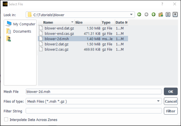
Global mesh replacement is performed by clicking in the Domain ribbon tab Zones group box), which opens the Select File dialog box (Figure 6.100: The Select File Dialog Box).
The steps for replacing the mesh using the Select File dialog box (Figure 6.100: The Select File Dialog Box) are as follows:
Select the replacement mesh from the appropriate folder.
By default, data is interpolated between matching zone pairs (that is, between the zones with the same names in both the current mesh and the replacement mesh). You can enable the Interpolate Data Across Zones option if you want to interpolate data across cell zones when replacing the mesh. This option is appropriate when the matching zone pairs do not have the same interior zone boundaries. Note that global conservation of data is not enforced when the Interpolate Data Across Zones option is enabled, so it should only be used when absolutely necessary. For best data interpolation, the zone boundaries of the replacement mesh should be coincident with those of the current mesh.
When running in parallel the replacement mesh gets partitioned such that matching cells reside on the same compute node. In some cases, differences in mesh resolution can cause the mesh to not be able to find its interpolation cell on the same compute node during interpolation. Fluent then automatically enables Interpolate Data Across Zones to ensure successful data interpolation across zones, even if you have not enabled the option. To avoid this behavior use the Scheme command:
(rpsetvar 'dynamesh/replace-mesh/partition-per-zone?
                #t)
. Note that using this command comes at the expense of requiring additional repartitioning steps.Click the button to replace the mesh.
The following limitations apply when replacing meshes:
The boundary conditions of the zones in the current mesh are mapped onto the zones with the same names in the replacement mesh, as described in Reading and Writing Boundary Conditions. If your replacement mesh contains zones for which no match is found, these zones will have the default boundary conditions for that zone type.
The replacement mesh is expected to be an Ansys Fluent mesh file in the legacy format (
.msh). You may select an Ansys Fluent legacy case file instead, but be aware that only the mesh information will be used and all of the setup information associated with that case file will be ignored. The default CFF files (.msh.h5or.cas.h5) may not be used as a replacement mesh.If you intend to select an Ansys Fluent legacy case file (
.cas) as the replacement mesh, you must first delete any defined non-conformal mesh interfaces in the case file (as described in Using a Non-Conformal Mesh in Ansys Fluent).You should ensure that the replacement mesh has the same mesh scaling as your current mesh. The data interpolation will not work properly if the meshes are scaled differently.
In some cases you may want to identify and display the face zones which are adjacent to a cell zone. You can do this using the Adjacency dialog box.
Domain → Zones
→ Adjacency...
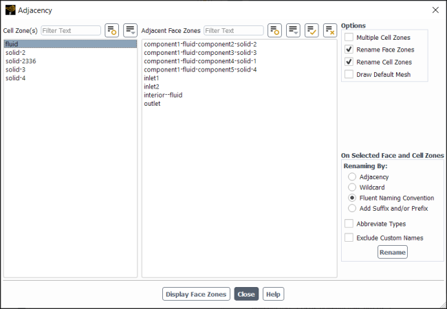
Using the Adjacency dialog box (Figure 6.101: The Adjacency Dialog Box) you can also optionally rename zones based on their adjacency or with default names based on zone type. The steps to use the Adjacency dialog box are:
Open the Adjacency dialog box by clicking in the Domain ribbon tab (Zones group box).
Select a zone under Cell Zone(s) to populate the Adjacent Face Zones list. You can use the 'Toggle Tree View' icon (
 ) to group the cell zones by type. If the Multiple Cell
Zones option is disabled, only one cell zone can be selected at a
time.
) to group the cell zones by type. If the Multiple Cell
Zones option is disabled, only one cell zone can be selected at a
time.Select the face zones you want to display in Adjacent Face Zones and click the Display Face Zones button.
Enable Draw Default Mesh to open the Mesh Display dialog box where you may choose to display mesh zones. These will be displayed permanently while others will be displayed as currently selected in the Adjacent Face Zones list. This is useful for finding your way through a new and complex mesh.
Enable Rename Face Zones if you want to rename or clean up some of the names that may cause confusion. See Renaming Zones Using the Adjacency Dialog Box for more information.
You can rename selected cell zones and/or face zones from the Adjacency dialog box after enabling Rename Face Zones and/or Rename Cell Zones. The following renaming methods are available:
- Rename by Adjacency

appends the name of the adjacent cell zone to the selected face zone(s). For example, if fluid is selected in the Cell Zone(s) and interior is selected in the Adjacent Face Zones list, then renaming by adjacency produces interior-fluid. If the name is already in use, the original zone ID is appended in addition in order to create a unique name. Note that it is best if you avoid using long cell zone names.
Note: Renaming by adjacency is only available for face zones and is not available for renaming cell zones.
- Rename by Wildcard
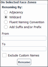
performs pattern matching of the selected zone names against the pattern in the From text box (with optional wildcards) and replaces a matching substring with the literal string in the To text box. Wildcard characters
*and?are interpreted as follows:A
*at the beginning and/or end of the From pattern matches zero or more characters at the beginning and/or end of the zone name that are retained during renaming with the rest of the name replaced by the To string.A
*used anywhere except at the beginning or end of the From pattern is not supported and may have unpredictable results.A
?matches exactly one character and is considered part of the string to be replaced. Multiple?characters can be used to match substrings of more than one character.
- Fluent Naming Convention
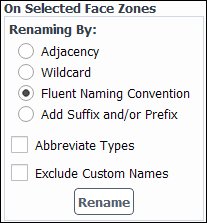
renames the selected surface to be a combination of the surface type and the surface ID. In the case of cell zones, the zone is renamed to be a combination of the zone type and zone ID.
- Add Suffix and/or Prefix
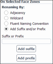
adds the provided text in the Suffix or Prefix field to either the beginning or end of the selected surface(s) name(s) or cell zone names. Click to add the provided text at the end of the name and click to add the provided text at the beginning of the name.
There are two additional options available for some renaming techniques:
Exclude Custom Names—excludes customized names (those that do not conform to a recognized pattern or match any default names) from renaming. This is a protective measure so as not to accidentally destroy your desired naming. Disabling this option will unconditionally rename all selected zones according to the specified renaming method and customized names will be permanently lost.
Abbreviate Types—abbreviates the zone type (for example,
vifor velocity inlet,intfor interior,ifcfor interface, and so on).
In a Fluent session that uses multiple processes, the mesh domain is automatically reordered when it is read, in order to increase memory access efficiency. The reordering uses the Reverse Cuthill-McKee algorithm [35], and is applied to cells and faces.
A typical output produced during the domain reordering at read is shown below:
Building...
     mesh
	auto partitioning mesh by Metis (fast),
	distributing mesh
		parts...,
		faces...,
		nodes...,
		cells...,
        bandwidth reduction using Reverse Cuthill-McKee: 3875/150 = 25.8333
The bandwidth is the maximum difference between neighboring cells in the zone—that is, if you numbered each cell in the zone list sequentially and compared the differences between these indices.
Internally, Ansys Fluent stores the computational mesh in meters, the SI unit of length. When mesh information is read, it is assumed that the mesh was generated in units of meters. If your mesh was created using a different unit of length (inches, feet, centimeters, and so on), you must scale the mesh to meters. To do this, you can select from a list of common units to convert the mesh or you can supply your own custom scale factors. Each node coordinate will be multiplied by the corresponding scale factor.
Scaling can also be used to change the physical size of the mesh. For instance, you
could stretch the mesh in the direction by assigning a scale factor of 2 in the
direction and 1 in the
and
directions. This would double the extent of the mesh in the
direction. However, you should use anisotropic scaling with caution, since
it will change the aspect ratios of the cells in your mesh.
Important:
If you plan to scale the mesh in any way, you should do so before you compute the view factors (as part of an S2S radiation problem), initialize the flow, or begin calculations. Any data that exists when you scale the mesh will be invalid.
It is a good practice to scale the mesh before setting up the case, especially when you plan to create mesh interfaces or shell conduction zones.
Scaling the mesh makes the graphics window [Out of Date]. Right-click in the graphics window and select Refresh Display to update the window.
You may have to click
 to see the object in the graphics window after refreshing the
display.
For the refresh of a mesh display, Fluent displays the surfaces that are currently selected in the global Mesh Display dialog box (accessed by clicking
 in the toolbar). In some instances this may result in the
refreshed display not matching what was originally displayed.
You have the option of scaling the entire mesh, or individual cell zones. For details, see the following:
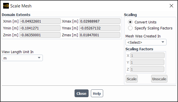
You will use the Scale Mesh Dialog Box (Figure 6.102: The Scale Mesh Dialog Box) to scale the entire mesh, either to change the unit of measurement or to apply custom scaling factors.
Setup →
![]() General
→ Mesh → Scale...
General
→ Mesh → Scale...
The procedure for scaling the mesh is as follows:
Use the conversion factors provided by Ansys Fluent by selecting Convert Units in the Scaling group box. Then indicate the units used when creating the mesh by selecting the appropriate abbreviation for meters, centimeters, millimeters, inches, or feet from the Mesh Was Created In drop-down list. The Scaling Factors will automatically be set to the correct values (for example, 0.0254 meters/inch).
If you created your mesh using units other than those in the Mesh Was Created In drop-down list, you can select Specify Scaling Factors and enter values for X, Y, and Z manually in the Scaling Factors group box (for example, the number of meters per yard).
Click the button. The Domain Extents will be updated to show the correct range in meters. If you prefer to use your original unit of length during the Ansys Fluent session, you can follow the procedure described below to change the unit.
As mentioned in Step 2. of the previous section, when you scale the mesh you do not change the units; you just convert the original dimensions of your mesh points from your original units to meters by multiplying each node coordinate by the specified Scaling Factors. If you want to work in your original units, instead of in meters, you can make a selection from the View Length Unit In drop-down list. This updates the Domain Extents to show the range in your original units and automatically changes the length unit in the Set Units Dialog Box (see Customizing Units). Note that this unit will be used for all future inputs of length quantities.
If you use the wrong scale factor, accidentally click the button twice, or want to undo the scaling for any other reason, you can click the button. “Unscaling” simply divides each of the node coordinates by the specified Scale Factors. (Selecting m in the Mesh Was Created In list and clicking on will not unscale the mesh.)
You can also use the Scale Mesh Dialog Box to change the physical size
of the mesh. For example, if your 2D mesh is 5 feet by 8 feet, and you want to model the
same geometry with dimensions twice as big (10 feet by 16 feet), you can enter
2 for X and Y in
the Scaling Factors group box and click
. The Domain Extents will be updated
to show the new range.
You have the ability to scale one or more individual cell zones. This could be useful, for example, if you append a case file to a mesh that is of a different scale. To scale zones, use the following text command:
mesh → modify-zones
→ scale-zone
You will be prompted to specify one or more cell zones, as well as the scaling factors in the coordinate directions.
Note: You cannot scale a zone that is conformally connected to a zone that is not being scaled.
You can “move” the mesh by applying prescribed offsets to the Cartesian
coordinates of all the nodes in the mesh. This would be necessary for a rotating problem if
the mesh were set up with the axis of rotation not passing through the origin, or for an
axisymmetric problem if the mesh were set up with the axis of rotation not coinciding with
the axis. It is also useful if, for example, you want to move the origin to a
particular point on an object (such as the leading edge of a flat plate) to make an XY plot
have the desired distances on the
axis.
You have the option of translating the entire mesh, or individual cell zones. For details, see the following:
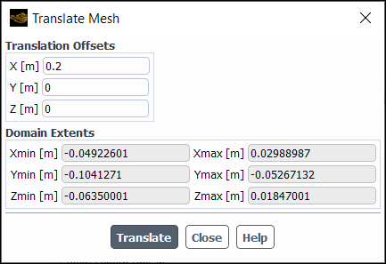
You can translate the entire mesh using the Translate Mesh Dialog Box (Figure 6.103: The Translate Mesh Dialog Box).
Domain → Mesh
→ Transform → Translate...
The procedure for translating the mesh is as follows:
Enter the desired translations in the
,
, and (for 3D)
directions (that is, the desired delta in the axes) in the X, Y, and Z text-entry boxes in the Translation Offsets group box. You can specify positive or negative real numbers in the current unit of length.
Click the button and redisplay the mesh. The Domain Extents will be updated to display the new extents of the translated mesh. (Note that the Domain Extents are purely informational; you cannot edit them manually.)
You have the ability to translate one or more individual cell zones. This could be useful, for example, if you append a case file to a mesh and they are not properly located relative to each other. To translate zones, use the following text command:
mesh → modify-zones
→ translate-zone
You will be prompted to specify one or more cell zones, as well as the offsets in the coordinate directions.
Note: You cannot translate a zone that is conformally connected to a zone that is not being translated.
The ability to rotate the mesh is analogous to the ability to translate the mesh in
Ansys Fluent. You can rotate the mesh about the ,
, or (for 3D)
axis and also specify the rotation origin. This option is useful in the
cases where the structural mesh and the CFD mesh are offset by a small angle.
You have the option of rotating the entire mesh, or individual cell zones. For details, see the following:
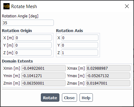
You can rotate the entire mesh using the Rotate Mesh Dialog Box (Figure 6.104: The Rotate Mesh Dialog Box).
Domain → Mesh
→ Transform → Rotate...
The procedure for rotating the mesh is as follows:
Specify the required Rotation Angle for the mesh. You can specify any positive or negative real number in the correct unit of angle.
In the Rotation Origin group box, enter X, Y, and (for 3D) Z coordinates to specify a new origin for the axis of rotation.
In the Rotation Axis group box, enter values for the X, Y, and (for 3D) Z axes to specify the vector for the axis of rotation.
Click the button and redisplay the mesh.
The Domain Extents will be updated to display the new extents of the rotated mesh. (Note that the Domain Extents are purely informational; you cannot edit them manually.)
You have the ability to rotate one or more individual cell zones. This could be useful, for example, if you append a case file to a mesh and they are not properly oriented relative to each other. To rotate zones, use the following text command:
mesh → modify-zones
→ rotate-zone
You will be prompted to specify one or more cell zones, as well as the rotation angle, origin, and axis components.
Note: You cannot rotate a zone that is conformally connected to a zone that is not being rotated.
Smoothing and face swapping are tools that complement mesh adaption by increasing the quality of the final numerical mesh. Smoothing repositions the nodes, and face swapping modifies the cell connectivity to achieve these improvements in quality.
Important: Only smoothing that is based on quality is recommended; face swapping and smoothing based on skewness or a Laplacian operator have more limitations, and support for them may be removed in a future release.
Important: Face swapping is applicable only to meshes with triangular or tetrahedral cells.
Important: Face swapping and smoothing based on skewness or a Laplacian operator are available only for serial cases; only quality-based smoothing can be used for parallel cases.
For additional information, see the following sections:
The three smoothing methods that are available in Ansys Fluent are:
quality-based smoothing
This method is the only recommended method, and is available for all types of meshes in serial and parallel.
Laplacian smoothing
This method is not recommended, though it is available for all types of meshes in serial (and is best suited for quadrilateral and hexahedral meshes).
skewness-based smoothing
This method is not recommended, though it is available for triangular and tetrahedral meshes in serial; it can be used alternatively with face swapping (see Combining Skewness-Based Smoothing and Face Swapping).
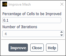
Smoothing that is based on quality is performed using the Improve Mesh Dialog Box (Figure 6.105: The Improve Mesh Dialog Box).
Domain → Mesh
→ Quality → Improve Mesh
Quality...
Ansys Fluent divides the mesh into a number of “bins”, each of which contain a certain number of cells. Improvements are attempted on the cells in those bins that exhibit the lowest orthogonal quality (as defined in Mesh Quality). As part of this method, you specify the percentage of the total number of cells, in order to determine how many bins are modified.
Note that this smoothing is similar to when you use the
mesh/repair-improve/improve text command. The advantage of
using the Improve Mesh dialog box rather than the text command is
that you can control the percentage of the cells that Ansys Fluent attempts to
improve.
To perform quality-based smoothing, do the following steps:
In the Improve Mesh Dialog Box (Figure 6.105: The Improve Mesh Dialog Box), enter the Percentage of Cells to be Improved.
Important: Quality-based smoothing will be CPU intensive if you specify a large value for the Percentage of Cells to be Improved. It is recommended that you enter a small value initially, and then perform the smoothing process multiple times, if necessary. Note that the maximum percentage allowed is 10%.
Specify the number of successive smoothing sweeps to be performed on the mesh in the Number of Iterations number-entry box. The default value is 4.
Click the button.
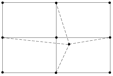
When you use this method, a Laplacian smoothing operator is applied to the unstructured mesh to reposition nodes. The new node position is the average of the positions of its node neighbors. The computed node position increment is multiplied by the relaxation factor (which is set to a value between 0.0 and 1.0). A value of zero for the relaxation factor results in no movement of the node, and a value of unity results in movement equivalent to the entire computed increment. Figure 6.106: Result of Smoothing Operator on Node Position illustrates the new node position for a typical configuration of quadrilateral cells. The dashed line is the original mesh and the solid line is the final mesh.
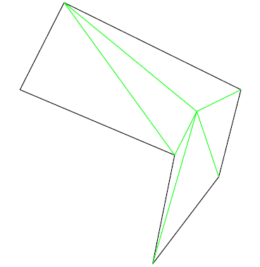
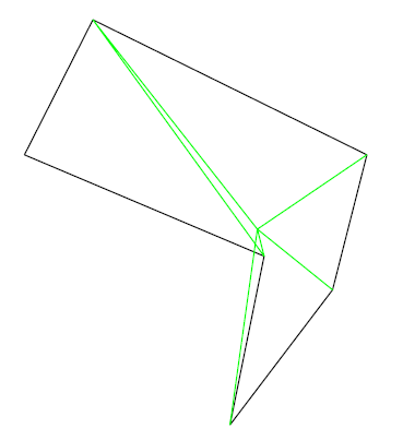
This repositioning strategy improves the skewness of the mesh, but relaxes the clustering of node points. In extreme circumstances, the present operator may create mesh lines that cross over the boundary, creating negative cell volumes. This is most likely to occur near sharp or coarsely resolved convex corners, especially if you perform multiple smoothing operations with a large relaxation factor. Figure 6.107: Initial Mesh Before Smoothing Operation illustrates an initial tetrahedral mesh before one unrelaxed smoothing iteration creates mesh lines that cross over each other (Figure 6.108: Mesh Smoothing Causing Mesh-Line Crossing).
The default smoothing parameters are designed to improve mesh quality with minimal adverse effects, but it is recommended that you save a case file before smoothing the mesh. If you apply a conservative relaxation factor and start with a good quality initial mesh, the frequency of failure due to smoothing is extremely low in two dimensions. However, corruption of the mesh topology occurs much more frequently in three dimensions, particularly with tetrahedral meshes.
The smoothing operator can also be applied repeatedly, but as the number of smoothing sweeps increase, the node points have a tendency to pull away from boundaries and the mesh tends to lose any clustering characteristics.
To perform Laplacian smoothing, enter the mesh/smooth-mesh
text command in the console and respond to the prompts as follows:
Enter
"laplace"for thetype of smoothing.Specify the number of successive smoothing sweeps to be performed on the mesh in response to the
number of iterationsprompt. The default value is 4.Specify the factor by which to multiply the computed position increment for the node in response to the
relaxation factorprompt. The lower the factor, the more reduction in node movement.
When you use skewness-based smoothing, Ansys Fluent applies a smoothing operator to the mesh, repositioning interior nodes to lower the maximum skewness of the mesh. Ansys Fluent will try to move interior nodes to improve the skewness of cells with skewness greater than the specified “skewness threshold”. This process can be very time consuming, so perform smoothing only on cells with high skewness.
Improved results can be obtained by smoothing the nodes several times. There are internal checks that will prevent a node from being moved if moving it causes the maximum skewness to increase, but it is common for the skewness of some cells to increase when a cell with a higher skewness is being improved. Thus, you may see the average skewness increase while the maximum skewness is decreasing.
Important: Carefully consider whether the improvements to the mesh due to a decrease in the maximum skewness are worth the potential increase in the average skewness. Performing smoothing only on cells with very high skewness (for example, 0.8 or 0.9) may reduce the adverse effects on the average skewness.
To perform skewness-based smoothing, enter the
mesh/smooth-mesh text command in the console and respond to
the prompts as follows:
Enter
"skewness"for thetype of smoothing.Specify the number of successive smoothing sweeps to be performed on the mesh in response to the
number of iterationsprompt. The default value is 4.Specify the minimum cell skewness value for which node smoothing will be attempted in response to the
skewness thresholdprompt. Ansys Fluent will try to move interior nodes to improve the skewness of cells with skewness greater than this value. By default, skewness threshold is set to 0.4 for 2D cases and 0.8 for 3D cases.
While it is not recommended over smoothing (and support for it may be removed in future releases), face swapping can be used to improve the quality of a triangular or tetrahedral mesh in the serial version of Ansys Fluent.
To perform face swapping, enter the mesh/swap-mesh-faces text
command repeatedly until the console report declares that 0 faces were swapped out. The
console report will display the total number of faces that were visited and tested for
possible face swapping.
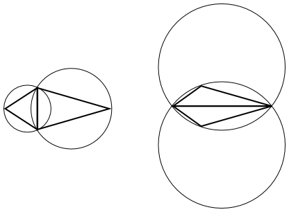
The approach for triangular meshes is to use the Delaunay circle test to decide if a face shared by two triangular cells should be swapped. A pair of cells sharing a face satisfies the circle test if the circumcircle of one cell does not contain the unshared node of the second cell. Figure 6.109: Examples of Cell Configurations in the Circle Test illustrates cell neighbors in the circle test. In cases where the circle test is not satisfied, the diagonal or face is swapped, as illustrated in Figure 6.110: Swapped Faces to Satisfy the Delaunay Circle Test.
Repeated application of the face-swapping technique will produce a constrained Delaunay mesh. If you have a Delaunay mesh, it is a unique triangulation that maximizes the minimum angles in the mesh. Thus, the triangulation tends toward equilateral cells, providing the most equilateral mesh for the given node distribution. For more information on Delaunay mesh generation, see Generating Tetrahedral Meshes in the Fluent Meshing section of the User’s Guide.
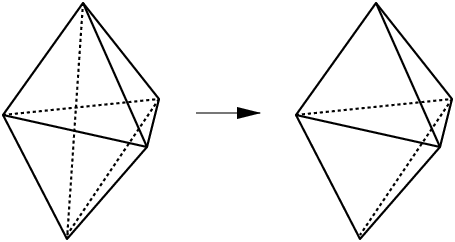
For tetrahedral meshes, face swapping consists of searching for configurations of three cells sharing an edge and converting them into two cells sharing a face to decrease skewness and the cell count (see Figure 6.111: 3D Face Swapping).
As mentioned in Skewness-Based Smoothing, skewness-based smoothing should usually be alternated with face swapping. Guidelines for this procedure are presented here.
Perform four smoothing iterations using a
skewness thresholdof 0.8 for 3D cases, or 0.4 for 2D cases.Swap until the number of faces swapped decreases to 0.
For 3D meshes, decrease the
skewness thresholdto 0.6 and repeat the smoothing/swapping procedure.
After performing mesh operations, the boundary layer zone may not satisfy the original
growth rate. When the boundary layer is composed of hex and/or wedge cells, you can restore
the desired growth rate by using the
mesh/redistribute-boundary-layer text command. You will be prompted
to enter a face zone and the desired growth rate. The face zone you specify must be adjacent
to the boundary layer zone that you want to redistribute.
>  mesh redistribute-boundary-layer
face zone id/name [] wall-fluid
growth rate [1.1] 1.2
Fluent will redistribute the nodes in a boundary region that extends into the mesh from the face zone you specify until one of the following criteria is encountered:
the edge of the domain
a change in zone
a change in element type
You can delete cells that are marked by a specified cell register. After the cells are deleted, one boundary zone of type symmetry is created for each cell zone at the faces that the deleted cells shared with their neighboring cells.
To delete cells marked by a cell register, perform the following steps:
Create a cell register to mark the cells you want to delete. For details, see Using Cell Registers. Note that to create some kinds of cell registers (such as one based on a field variable), you must first initialize the solution.
Delete the cells by using the following text command:
mesh→modify-zones→delete-cell-by-markThe names of any symmetry boundary zones created as part of this deletion are printed in the console.
Note:
The deletion of cells in a cell register is not supported with the following:
overset meshes
shell conduction walls
There is no way to undo the deletion, so it is recommended that you save a copy of the case file before deleting.
overset meshes
shell conduction walls


