


In Ansys Fluent it is possible to use a mesh that has non-conformal interfaces, that is, boundaries between cell zones that connect to each other in which the mesh node locations are not identical. Such non-conformal interfaces permit the cell zones to pass fluxes from one mesh to another.
To compute the flux across the non-conformal boundary, Ansys Fluent must first compute the intersection between the interface zones that make up the boundary. In the case of a solid-to-solid zone interface of the same material or a fluid-to-fluid zone interface, the resulting intersection produces an interior zone where the two interface zones overlap (see Figure 6.30: Completely Overlapping Mesh Interface Intersection). In the case of a solid-to-solid zone interface of different materials or a fluid-to-solid zone interface, the boundary is treated as a coupled wall (see The Coupled Wall Option).
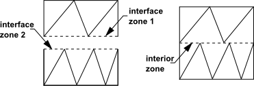
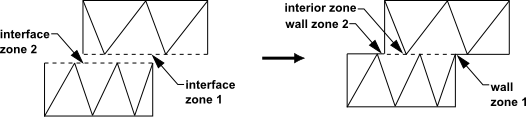
If one of the interface zones extends beyond the other (Figure 6.31: Partially Overlapping Mesh Interface Intersection), by default Ansys Fluent will create additional boundary zones for the portion(s) of the boundary where the two interface zones do not overlap; these are referred to as "non-overlapping zones", and you can change their settings and/or zone type at your discretion.
Fluxes across the mesh interface are computed using the faces resulting from the intersection of the two interface zones, not from the interface zone faces.
In the example shown in Figure 6.32: Two-Dimensional Non-Conformal Mesh Interface, the interface zones are composed of faces A-B and B-C, and faces D-E and E-F.
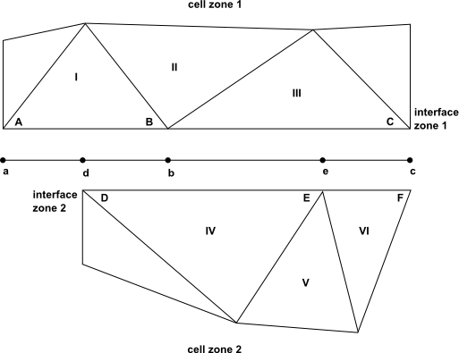
The intersection of these zones produces the faces a-d, d-b, b-e, and e-c. Faces produced in the region where the two cell zones overlap (d-b, b-e, and e-c) are grouped to form an interior or coupled wall zone (depending on the types of the adjacent cell zones), while the remaining face (a-d) forms a wall zone.
To compute the flux across the interface into cell IV, face D-E is ignored and instead faces d-b and b-e are used to bring information into cell IV from cells I and III.
While the previous discussion described the default treatment of a non-conformal interface, there are several options you can enable at the interface in order to revise the treatment of the fluxes and/or reduce the memory usage and processing time:
periodic boundary condition
periodic repeats
coupled wall
matching
mapped
static
Note: Only the coupled wall option is available for mesh interfaces created using the default one-to-one interface creation method.
These non-conformal interface options are described in the following sections.
Non-conformal interfaces can be used to implement a periodic boundary condition like that described for conformal periodic boundaries (see Periodic Boundary Conditions). The advantage of using a mesh interface is that, unlike the standard periodic boundary condition, the nodes of the two zones do not have to match one-for-one.
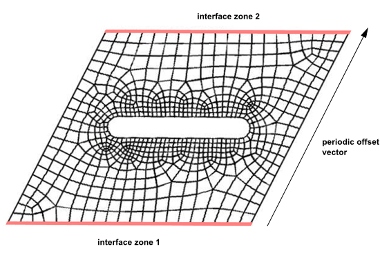
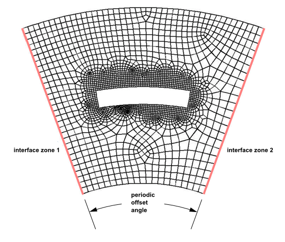
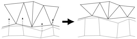
The interface zones that utilize the periodic boundary condition option (Figure 6.33: Non-Conformal Periodic Boundary Condition (Translational) and Figure 6.34: Non-Conformal Periodic Boundary Condition (Rotational)) are coupled in the manner described in the previous section, except that the zones do not overlap (that is, the zones are not spatially coincident at any point). In order to generate the new faces that will be used to compute the fluxes across the interface, the nodes of the first zone are either translated or rotated (about a given axis) onto the other zone. The distance/angle that the nodes are translated/rotated is called the "periodic offset". The new faces will be defined between all of the combined nodes, and then applied to each of the original zones.
Note: The Matching option is enabled by default with the Periodic Boundary Condition option.
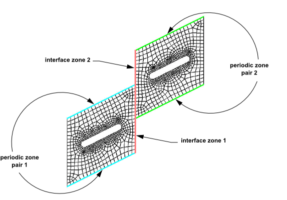
The periodic repeats option is appropriate when each of the interface zones is adjacent to a non-conformal periodic interface or a pair of conformal periodic zones (see Figure 6.35: Translational Non-Conformal Interface with the Periodic Repeats Option and Figure 6.36: Rotational Non-Conformal Interface with the Periodic Repeats Option). The periodic repeats option takes into account the repeating nature of the flow solutions in the two cell zones in the following manner. Wherever the interface zones overlap (that is, wherever interface zone 1 and 2 are spatially coincident), the fluxes on either side of the interface are coupled in the usual way. The portion of interface zone 1 that does not overlap is coupled to the non-overlapping portion of interface zone 2, by translating or rotating the fluxes by the periodic offset. This is similar to the treatment of non-conformal periodic boundary conditions. The periodic repeats option is typically used in conjunction with the sliding mesh model when simulating the interface between a rotor and stator.
Note: The periodic repeats option is not supported if the interface zone is adjacent to a solid zone.

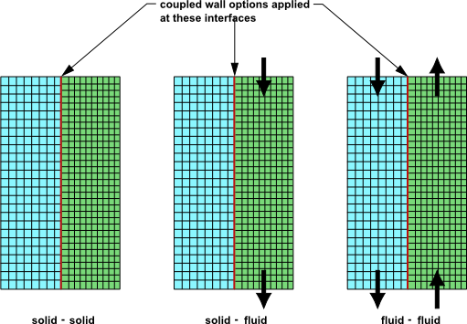
As described previously, the typical function of non-conformal interfaces is to couple fluid zones, so as to permit fluid flow to pass from one mesh interface to the other. Another available option is to create a coupled wall boundary at the interface. In such a case, fluid flow would not pass across the interface, as the interface is acting as a wall zone. Coupled wall heat transfer, on the other hand, would be permitted. Such treatment is applied by default in the case of a solid-to-solid zone interface of different materials or a fluid-to-solid zone interface. For fluid-to-fluid zone interfaces, you must enable the Coupled Wall option to have such treatment; for example, you can model a thin wall or baffle separating the two fluid zones. Figure 6.37: Non-Conformal Coupled Wall Interfaces illustrates coupled walls with both solid and fluid zones.
Note that coupled walls can also make use of the periodic repeats option. That is, both options can be invoked simultaneously. For details see Using a Non-Conformal Mesh in Ansys Fluent.
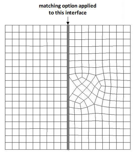
When two interface zones do not match well (which could result from different mesh topologies, geometric misalignment, or the existence of large gaps), wall zones will be created on the interface. If, in such cases, you want to have only internal zones generated on the interface (that is, interior or wall / shadow pairs), it is best to use a matching interface. If the interface zones are completely overlapping (see Figure 6.30: Completely Overlapping Mesh Interface Intersection) as opposed to partially overlapping (see Figure 6.31: Partially Overlapping Mesh Interface Intersection) and so no wall zones are expected to be created on the mesh interface, it is recommended that you select the Matching option.
Note: The Matching option is enabled by default with the Periodic Boundary Condition option.
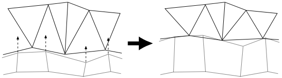
Figure 6.38: Matching Non-Conformal Wall Interfaces below shows two interface zones that do not match up well in the center—the interface zone on the right has an inverted spike. Even with such a large mismatch, the Matching option still enables you to create an interface with only the interior zone.
When the Matching option is selected, Ansys Fluent checks if one interface zone sits on top of the other and displays messages if there is a penetration of cell zones that are connected through a mesh interface (therefore making the interface invalid for use). Since the severity of zone penetration is different for matching interfaces and non-matching interfaces, Ansys Fluent displays different messages accordingly.
For example, for non-matching interfaces:
Info: Interface zones penetrate each other for mesh interface (interface-name). This could adversely
affect your solution.
Likewise, for matching interfaces:
Warning: Interface zones penetrate each other for mesh interface (interface-name).
This could generate left-handed faces on the interface and make it invalid for use.The Mapped option is an alternative approach for modeling coupled walls between zones. This approach provides better handling for interface zones that penetrate each other or have gaps between them. The Mapped option is useful in situations where using the standard non-conformal interface formulations causes the simulation to fail (as may occur when there is interface penetration or gaps between interfaces, causing the creation of left-handed faces at the interface).
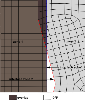
Figure 6.39: Non-Conformal Mapped Interface with a Gap and Penetration shows significant penetration between the two interface zones and large gap. The mapped option allows you to create a coupled wall even with the large amount of penetration and gap shown in this image.
The Mapped option only works in conjunction with the Coupled Wall option. Enabling the Mapped automatically enables Coupled Wall.
You can use the Mapped Interface Options Dialog Box to modify the global settings for the mapped interfaces, as well as to convert existing mesh interfaces (either all of them or just those that have penetrating zones) to use the Mapped option.
You can confirm that you created good quality mapped interfaces by performing a mesh
check. If you have mapped interfaces that did not pass the quality check, Fluent will
suggest that you use the text command
define/mesh-interface/improve-quality, which allows you to
increase the interface tolerance to improve the quality of the mapped interfaces.
In problems set up in version 19.2 or earlier, where you have a solid zone adjacent to
a fluid zone (conjugate heat transfer) with a mapped mesh interface between them, it is
recommended you switch from the explicit coupling method to the implicit method using the
text command /define/models/cht/implicit-coupling?. The implicit
method produces better convergence behavior compared to the explicit method for these
fluid-solid pairs. Note that the implicit method is the now the default.
Note the following limitations when using the Mapped option:
The Mapped option can only be applied if at least one side of the interface consists of only solid zones.
The Mapped option is not compatible with shell conduction.
Thermal coupling calculations will not be performed at mapped interfaces for the Eulerian multiphase model.
No other interface options besides Coupled Wall are allowed with the Mapped option.
For the S2S model, the Face to Face basis for the view factors is not compatible with mapped interfaces for polyhedral meshes.
Mapped interfaces are not supported with the density-based solver.
Mapped interfaces are not supported with the Lagrangian discrete phase model.
Mapped interfaces are not supported with moving / deforming meshes.
For a default mesh interface or when the Coupled and/or Matching options are enabled, Ansys Fluent will automatically create zones that will be needed if the interface should change due to motion (from moving reference frames or sliding meshes) or deformation. If you know in advance that the interface zones will not be moving or deforming relative to each other at the interface, then (and only then) it is recommended that you enable the Static option. The Static option prevents the creation of such zones, and thus reduces the memory usage and processing time (for both the creation of the interface and the running of the calculation). This reduction can be significant, especially when there are many zones on both sides of the interface.
Warning: If the Static option is applied at an interface that does end up undergoing relative motion or deformation, the results will be incorrect.
Note that the Static option is not limited to steady-state cases.
The following sub-sections describe the automatic naming conventions for each type of non-conformal interface. Note that in these descriptions:
<mesh interface name> is user specified
<connection number side 1> is a value between 1 and m, where m is the number of zones in interface zone side 1
<connection number side 2> is a value between 1 and n, where n is the number of zones in interface zone side 2
<side number> is 1 or 2
The automatic naming convention for the non-overlapping zones is as follows: <interface zone name> - non-overlapping.
The automatic naming convention for interface wall zone side 1 is as follows: <mesh interface name> - wall1 - <connection number side 1> - <connection number side 2>.
The automatic naming convention for interface wall zone side 2 is as follows: <mesh interface name> - wall1 - <connection number side 1> - <connection number side 2> - shadow.
The automatic naming convention for interface interior zones from a one-to-one pairing (the default) is as follows: <mesh interface name>.
The automatic naming convention for interface interior zones that are from a many-to-many pairing is as follows: <mesh interface name> - interior - <connection number side 1> - <connection number side 2>.
The automatic naming convention for the non-overlapping zones is as follows: <interface zone name> - non-overlapping.
The automatic naming convention for interface interior zones is as follows: <mesh interface name>.
The automatic naming convention for interface interior zones is as follows: <mesh interface name> - periodic. Note that unnamed zones may be created for use in the solver and cannot be changed or modified by the user.
The automatic naming convention for the non-overlapping zones is as follows: <interface zone name> - non-overlapping.
The automatic naming convention for interface wall zones from a one-to-one pairing (the default) is as follows: <mesh interface name> and <mesh interface name> - shadow.
The automatic naming convention for side 1 of interface wall zones that are from a many-to-many pairing is as follows: <mesh interface name> - wall1 - <connection number side 1> - <connection number side 2>; and then interface wall zone side 2 is named: <mesh interface name> - wall1 - <connection number side 1> - <connection number side 2> - shadow. For example:
> define/mesh-interfaces/list

List of Mesh Interfaces


Interface Name:     cw:01
Interface Options:  Coupled


       Description                      Name               ID         Area        Area Percentage
---------------------------  --------------------------  -------  --------------  ----------------
      Interface-Zone-Side-1                          a2       17    0.1707190424
      Interface-Zone-Side-1                          a1       13    0.1707191467
      Interface-Zone-Side-2                          b1        4   36.7499923706
Non-Overlapping-Zone-Side-2          b1-non-overlapping       53   36.4085540771        99.070915%
      Interface-Wall-Zone-1             cw:01-wall1-1-1       50    0.1706306934        99.948250%
      Interface-Wall-Zone-1             cw:01-wall1-2-1       49    0.1706308126        99.948257%
      Interface-Wall-Zone-2      cw:01-wall1-1-1-shadow       54    0.1706306934         0.464301%
      Interface-Wall-Zone-2      cw:01-wall1-2-1-shadow       55    0.1706308126         0.464302%
The automatic naming convention for interface interior zones is as follows: <mesh interface name> - interior - <connection number side 1> - <connection number side 2>.
The automatic naming convention for the non-overlapping zones is as follows: <interface zone name> - non-overlapping.
The automatic naming convention for interface wall zones is as follows: <mesh interface name> - wall <side number> - <connection number side 1> - <connection number side 2>.
For example,
> define/mesh-interfaces/list

List of Mesh Interfaces


Interface Name:     map:01
Interface Options:  Mapped


   Description                         Name               ID          Area         Area Percentage
---------------------------  -------------------------  -------  ---------------  ----------------
      Interface-Zone-Side-1                         a1       18   1.01046020e-03
      Interface-Zone-Side-2                         b1        6   1.01029174e-03
Non-Overlapping-Zone-Side-1         a1-non-overlapping       30   1.10513203e-04          10.9369%
Non-Overlapping-Zone-Side-2         b1-non-overlapping       31   1.10303146e-04          10.9179%
 Interface-Wall-Zone-Side-1           map:01-wall1-1-1       14   8.99947016e-04          89.0631%
Interface-Wall-Zone-Side-2 map:01-wall2-1-1 29 8.99988518e-04 89.0820%In the current version of Ansys Fluent, non-conformal interface calculations are handled using one of three approaches depending on the type of interface. Coupled Wall interfaces are handled using interface boundary metrics and Mapped interfaces use a projection approach. The interface boundary metrics and projection approach are both robust algorithms that avoid creating left-handed faces and are particularly useful when you have complex geometries.
The remaining types of non-conformal interfaces are handled using a virtual polygon approach. The virtual polygon approach stores the area vector and centroid of the polygon faces. This approach does not involve node movement and cells are not necessarily water-tight cells. Hence gradients are corrected to take into account the missing face area. Note that in transient cases, the stationary non-conformal interfaces will be automatically preserved by Ansys Fluent during mesh update.
Previous versions (16.0 and earlier) of Fluent used the virtual polygon approach for all non-conformal interfaces. The interface boundary metrics is a more robust approach for creating coupled wall interfaces than the virtual polygon approach because it avoids creating left-handed faces. Older versions of Fluent (6.1 or earlier) used a triangular face approach, which triangulated the polygon intersection faces and stored triangular faces. This approach involved node movement and water-tight cells, and was not as stable as the virtual polygon approach. Note that case files created in releases prior to 16.0 can be read and run normally in the current version of Fluent unless you recreate any of the interfaces. Recreated coupled wall interfaces will use interface boundary metrics and all other recreated interfaces will use the virtual polygon approach.
For a sliding mesh case that has interface zones that do not
match well at the mesh interface, the resulting mesh may have left-handed faces. Such faces
can cause the mesh to be invalid, and so Ansys Fluent automatically attempts to make the faces
"right handed". If any left-handed faces remain, you can remove them using the
define/mesh-interfaces/remove-left-handed-interface-faces? text
command.
Left-handed cells can also be created for the geometries that contain sharp edges and corners, which may affect the final solution. For such geometries, you should first separate the zones and then create the interfaces separately to get the better solution.
The additional input of the angle/translation vector at the
angle/translation-vector prompt in the console may be required to
recreate face-periodic interfaces. Also, with the current mesh interface algorithm in
parallel, there is no need for encapsulation.
This section describes the requirements and limitations of non-conformal meshes:
The mesh interface can be of any shape (including a non-planar surface, in 3D), provided that the two interface boundaries are based on the same geometry. If there are sharp features (for example, 90-degree angles) or curvature in the mesh, it is especially important that both sides of the interface closely follow that feature.
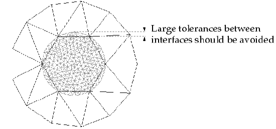
For example, consider the case of two concentric circles that define two fluid zones with a circular, non-conformal interface between them, as shown in Figure 6.40: A Circular Non-Conformal Interface. Because the node spacing on the interface edge of the outer fluid zone is coarse compared to the radius of curvature, the interface does not closely follow the feature (in this case, the circular edge.)
Important: The maximum tolerance between two interfaces should not be larger than their adjacent cell size at that location; that is, no cell should be completely enclosed between two interfaces.
Non-conformal interface surfaces can be visualized, but they do not participate in postprocessing operations. That is, they will show zero values while the corresponding parent walls are non-zero.
If you create a single mesh with multiple cell zones separated by a non-conformal boundary, you must be sure that each cell zone has a distinct face zone on the non-conformal boundary.
The face zones for two adjacent cell zones will have the same position and shape, but one will correspond to one cell zone and one to the other. It is also possible to create a separate mesh file for each of the cell zones, and then merge them as described in Reading Multiple Mesh/Case/Data Files.
All periodic zones must be correctly oriented (either rotational or translational) before you create the non-conformal interface.
In order for the periodic boundary condition option or periodic repeats option to be valid, the edges of the second interface zone must be offset from the corresponding edges of the first interface zone by a uniform amount (either a uniform translational displacement or a uniform rotation angle). This is not true for non-conformal interfaces in general.
The periodic boundary condition option has the additional requirement that the angle associated with a rotationally periodic must be able to divide 360 without remainder.
The periodic repeats option requires that some portion of the two interface zones must overlap (that is, be spatially coincident).
The periodic repeats option requires that the non-overlapping portions of the interface zones must have identical shape and dimensions. If the interface is part of a sliding mesh, you must define the mesh motion such that this criterion is met at all times.
Note that for 3D cases, you cannot have more than one pair of conformal periodic zones adjacent to each of the interface zones.
You must not have a single non-conformal interface where part of the interface is made up of a coupled two-sided wall, while another part is not coupled (that is, the normal interface treatment). In such cases, you must break the interface up into two interfaces: one that is a coupled interface, and the other that is a standard fluid-fluid interface. See Using a Non-Conformal Mesh in Ansys Fluent for information about creating coupled interfaces.
For simulations that involve the Fluent, Mechanical, and Meshing applications, meshing problems can arise in instances where there are multiple regions and contacts between them. In Fluent, a zone can only exist in a single contact region. The Mechanical and Meshing applications both use a different approach concerning contact regions when compared to Fluent.
Fluid zones designated as 3D fan zones cannot have non-conformal interfaces.
When you read a non-conformal interface case file into meshing mode and later switched to the solution mode, note the following limitations:
Zone IDs may match, however, the corresponding zone names may be inconsistent.
Boundary conditions on intersected threads are not preserved.
Unassociated (dangling) non-conformal interface (NCI) surfaces remain present.
If your multiple-zone mesh includes non-conformal boundaries, check if the mesh meets all the requirements (listed in Requirements and Limitations of Non-Conformal Meshes). This ensures that Ansys Fluent can obtain a solution on the mesh. Then do the following:
Read the mesh into Ansys Fluent. If you have multiple mesh files that have not yet been merged, first follow the instructions in Reading Multiple Mesh/Case/Data Files to merge them into a single mesh.
Change the type for all of the zones that make up the non-conformal boundaries as needed. When using the default one-to-one interface creation method, change them to interface or wall if you plan to use the Mesh Interfaces or Create Mesh Interfaces dialog box; if you instead plan to use the right-click menu in the outline view or the text command interface, they can be any external boundary zone type. When using the many-to-many interface creation method, you must change them all to type interface. For details on changing the zone type, see Changing Cell and Boundary Zone Types.
 Setup →
  Boundary
Conditions
Boundary
Conditions By default, the one-to-one interface method is enabled for creating mesh interfaces, so that a single zone is assigned to each side of all of the resulting mesh interfaces. This method has the following advantages over the many-to-many method (which can produce mesh interfaces that have multiple zones on one or both sides):
It allows you to have single boundary zones be a part of multiple mesh interfaces, so that it is not necessary to break up large boundary zones in the meshing mode of Fluent prior to creating mesh interfaces (which may compromise the quality of the interface, and is not available for polyhedral meshes). This can improve the accuracy / robustness of the simulation.
It allows additional boundary zone types besides interface zones to form the two sides a mesh interface:
When using the Mesh Interfaces or Create Mesh Interfaces dialog box (as described in later steps), you can select wall zones. This can simplify your setup when your case has a large number of wall zones, if only some of them will be part of a non-conformal interface.
When using the text command interface or selecting them in the outline view and using the right-click menu (Mesh Interfaces / Create), you can select any type of external boundary zone (that is, any zone that is connected with the cells on only side).
It allows you to create a mesh interface between two zones that are not overlapping at all. This can be useful when setting up a sliding mesh simulation in which the zones begin without overlap, and then slide into a position that includes overlap. Note that to do this, you must select only two zones at a time in the Mesh Interfaces dialog box, or you can select two groups of zones in the Create Mesh Interfaces dialog box.
You must weigh the advantages listed above against the following limitations:
No interface options can be enabled at the time of creation, except for the coupled wall option that is automatically enabled for solid-to-fluid/solid mesh interfaces.
The only editing you can do to such a mesh interface after it has been created is to change the name and/or apply a coupled wall boundary condition (as described in a later step).
You may want to disable the one-to-one interface creation method in order to use certain options, such as the Periodic Boundary Condition option or the Mapped option. You can disable the one-to-one method by using the following text command:
define→mesh-interfaces→one-to-one-pairing?Note that all of the mesh interfaces in a case file should be created using the same method. If mesh interfaces already exist and you use the previous text command to change the method, you will be prompted to authorize that the existing mesh interfaces are deleted (when switching to the many-to-many method) or converted (when switching to the one-to-one method). When converting, all incompatible settings will be disabled. Conversion can be useful if you want to update old case files that were created in an earlier version of Fluent when the one-to-one method was not available or was not enabled by default.
(optional) When using the default one-to-one interface creation method, there are optional settings that may be useful:
You can define settings related to the names of the resulting mesh interfaces.
One option pertains to the suffix added to the end of the name: by default the suffix includes the names of the associated boundary zones, and you can use the following text command to instead specify that the suffix is omitted, replaced with the IDs of the boundary zones, or replaced with the names of the adjacent cell zones.
define→mesh-interfaces→auto-options→naming-optionYou can also change the default interface name prefix by using the following text command:
define→mesh-interfaces→auto-options→set-default-name-prefixYou can enable the following text command so that the boundary conditions of the original zones are copied to the resulting coupled wall pair when a mesh interface is created at a solid-to-solid zone interface of different materials or a fluid-to-solid zone interface. This can save you from having to edit such zones later on. Note that the coupled wall pair is thermally coupled.
define→mesh-interfaces→coupled-interfaces-inherit-bcs?If you want to ensure that mesh interfaces are only created between different cell zones, you can enable the following text command:
define→mesh-interfaces→auto-options→pairing-between-different-cell-zones-only?When more than two zones are selected in the Boundary Zones group box in the Mesh Interface dialog box, default tolerances are used to determine which zones can be paired up to make the mesh interfaces. These default tolerances may not be suitable for your application if there are gaps between interfaces, multiple mesh interfaces in proximity, or under-resolved interfaces with a large curvature. If you find that the default tolerances are not producing the expected number of mesh interfaces, or the correct mesh interface areas, you can use the following text command to enable adjustable tolerances:
define→mesh-interfaces→auto-options→set-one-to-one-pairing-toleranceWith adjustable tolerances enabled, the tolerances are evaluated using the product of a specified length factor (with a default value of 1) and the largest mesh length scale of the interface boundaries. You can reduce the length factor if the resulting interface areas are too large or if boundary zones that you do not want paired are paired. An increase in the length factor is recommended if any expected interfaces are not created, or if the intersection areas are smaller than expected.
You can use the following text command to set the minimum area percentage of overlap for mesh interface creation. If zones are paired using the automatic method (as described in a later step), after the mesh interfaces are created, a check will be done: if the area that the two zones overlap divided by the area of the zone is less than this value for both zones in any mesh interface, then that mesh interface will be deleted. This can help you avoid unnecessary or unintentional mesh interfaces. By default the minimum area percentage is set to 0, so no pairings are deleted. When you are setting up a sliding mesh simulation in which the zones begin with little or no overlap and then slide into a position that includes more overlap, you should make sure the minimum area percentage is set such that it does not delete your intended mesh interface.
define→mesh-interfaces→auto-options→set-minimum-area-percentage
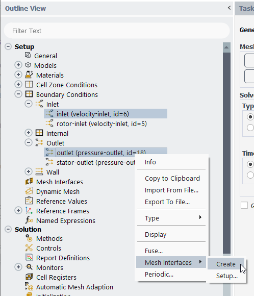
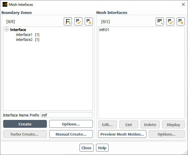
Open the Mesh Interfaces Dialog Box.
Setup → Mesh Interfaces

Create all of the mesh interfaces that use the periodic or periodic repeats option. To do so, you must disable the one-to-one interface creation method and use the manual method by clicking the button to open the Create/Edit Mesh Interfaces Dialog Box. For details, see Manually Creating Many-to-Many Mesh Interfaces.
If you want to easily create many mesh interfaces between boundary zones that do not currently overlap (for example, for a sliding mesh simulation), you must ensure that the default one-to-one interface creation method is selected and click the button to open the Create Mesh Interfaces. For details, see Manually Creating Many Non-Overlapping Mesh Interfaces.
Create all of the mesh interfaces that do not use the periodic or periodic repeats option, using the automatic method. As part of this method, Fluent will automatically determine which of the selected interface boundary zones can be grouped together to form the two sides of one or more mesh interfaces.
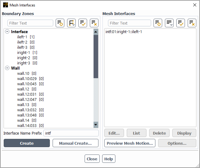
To use the automatic method, perform the following steps in the Mesh Interfaces dialog box:
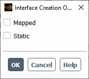
(optional) If you have disabled the one-to-one interface creation method, you can click the button in the Boundary Zones group box to open the Interface Creation Options Dialog Box, and enable the settings that you want applied to all of the resulting interfaces.
You can specify that the mapped option is applied to all of the resulting interfaces for which at least one side of the interface consists of only solid zones, by enabling the Mapped option. Note that the mapped option will be applied regardless of the mesh quality, and the tolerance used for mapping will be that specified in the Mapped Interface Options Dialog Box. For more information about the mapped option, see The Mapped Option.
You can specify that all of the resulting interfaces use the Static option, if and only if you know that the interface zones will not be moving or deforming relative to each other at the interface. While you will have the ability to enable the static option after the interfaces are created, doing so prior to creation avoids the creation of unnecessary zones (and thus saves memory usage and processing time, which can be significant when you have selected many Boundary Zones in the Mesh Interfaces dialog box).
Select the zones in the selection list in the Boundary Zones group box that you want paired. You may want to select only some of the zones, such as when you want the resulting mesh interfaces to have different settings in the Interface Creation Options dialog box (as described in the previous step), or different name prefixes (as described in the steps that follow); for example, you could select only the interface zones from the front half of a model, and then have all of the resulting mesh interfaces named with the prefix "front". For a case in which the zones begin with no overlap, and will later move into a position that includes overlap (such as a sliding mesh simulation), you must select only two zones at a time if you want to use the Mesh Interfaces dialog box; if you want to select more than two zones at a time, you would need to use the Create Mesh Interfaces dialog box instead, as described in Manually Creating Many Non-Overlapping Mesh Interfaces.
Note that each zone in this list has a number in brackets on the right side (for example, [0]). This number indicates how many mesh interfaces it is already a part of, as a result of any previous acts of mesh interface creation. Note that a boundary zone can only be used in multiple mesh interfaces when those mesh interfaces are created when the default one-to-one interface creation option is enabled.
Enter the Interface Name Prefix you want applied to all of the resulting interfaces.
Click the button in the Mesh Interfaces dialog box to create the interfaces. The resulting interfaces will be added to the Mesh Interfaces list; note that if you select an item in the list, the associated zones will be highlighted in the Boundary Zones group box (and vice versa). Details about the creation process will be printed in the console, including (for one-to-one pairings) a list of the resulting mesh interfaces with the area percentage that each boundary zone overlaps the other.
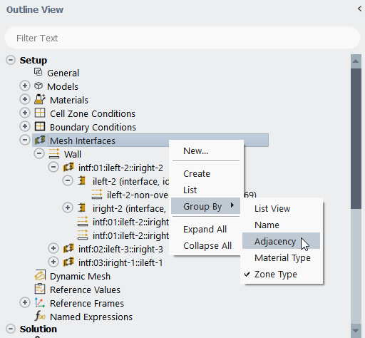
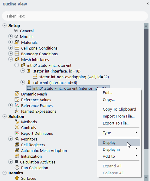
After creating mesh interfaces, you can manage them from the outline view tree (under Setup / Mesh Interfaces) or from the Mesh Interfaces dialog box. Note that for cases with only one-to-one mesh interfaces:
The individual mesh interfaces listed in the outline view tree have nodes that can be expanded to list all of the associated boundary zones (which have icons to indicate their type). By default, this also includes the associated non-overlapping zones and interior zones, and this is the only place they are listed in the outline view; you can choose to instead have them listed under Setup / Boundary Conditions under their zone types, by enabling the Show interface children option in Appearance branch of the Preferences dialog box (accessed through File/Preferences...).
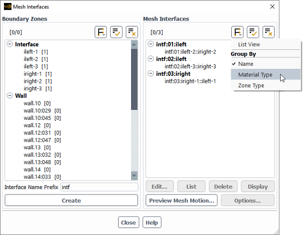
Using the right-click menu, you can choose to display the mesh in a list view or grouped by the names, the adjacent cell zones, the materials on either side (for example, fluid-fluid), and the zone types (that is, whether it includes an internal boundary or a wall because the adjacent cell zones are similar or dissimilar material types, respectively).
All of the outline view tree grouping options (except for the adjacent cell zones option) are also available in the Mesh Interfaces group box of the Mesh Interfaces dialog box, through the button.
For mesh interfaces that were created using the default one-to-one interface creation method, you can edit them in the following ways:
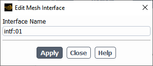
To edit the name, make a selection from the Mesh Interfaces list, click , and then revise the Interface Name in the Edit Mesh Interface dialog box that opens.
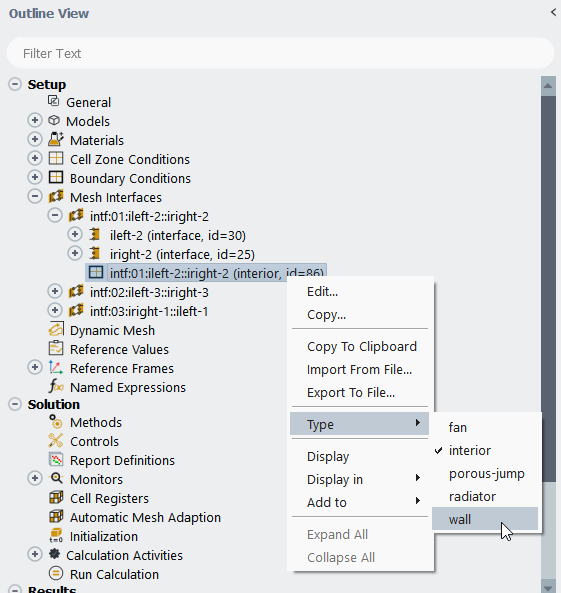
To model a thermally coupled wall at a mesh interface between two fluid zones, right-click the associated interface interior zone in the outline view; by default it is under the associated mesh interface under Setup / Mesh Interfaces, and has the same name as the mesh interface. Then hover over Type and select wall from the menu that opens.
Note: In the case of a solid-to-solid zone interface of different materials or a fluid-to-solid zone interface, by default it is treated as a coupled wall. Therefore, no action is required in the outline view tree to set up such an interface.
For mesh interfaces that were created with the one-to-one interface creation method disabled, you can revise them by making a selection from the Mesh Interfaces list, clicking , and then completing the setup in the Edit Mesh Interfaces Dialog Box that opens.
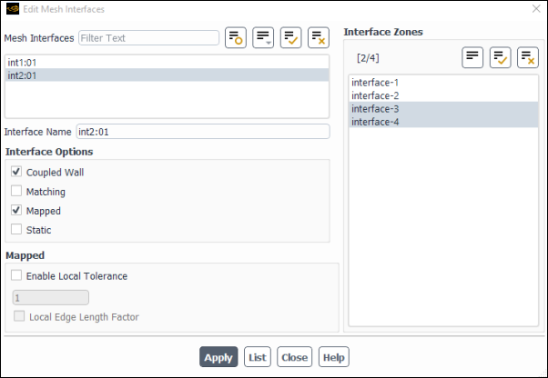
In the Edit Mesh Interfaces dialog box, select the Mesh Interfaces you want to change, revise the settings, and click . You can edit the Interface Name and/or the Interface Zones that make up the interface (provided that the zones you select are unassigned and located appropriately), though such changes are only allowed if you select a single interface. You can select one or more interfaces and enable the following Interface Options; note that you can click the
 button to group the interfaces in the list by their currently
enabled interface option(s), which allows you to select / deselect all those of a
particular type by simply clicking the top-level branch.
button to group the interfaces in the list by their currently
enabled interface option(s), which allows you to select / deselect all those of a
particular type by simply clicking the top-level branch.Enable Coupled Wall if you would like to model a thermally coupled wall between two fluid zones that share a non-conformal interface.
Note: In the case of a solid-to-solid zone interface of different materials or a fluid-to-solid zone interface, by default it is treated as a coupled wall. Therefore, no action is required in the Edit Mesh Interfaces dialog box to set up such an interface.
Enable the Matching option if only internal zones should be created (that is, interior or wall / shadow pairs), since the interface zones on both sides are aligned. With the Matching option, even interface zones that are not perfectly aligned are treated as if they are; however, if the discrepancy between the interface zones on both sides exceeds default thresholds, then warning messages will be displayed. See Matching Option for more information about the recommended uses of this option.
Enable the Mapped option when there is penetration or large gaps between interface zones. Note that at least one side of the interface must consist of only solid zones. For additional information, see The Mapped Option.
Enable Enable Local Tolerance in the Mapped group box for the selected interface, if you want to override the global tolerance defined for Mapped Tolerance in the Mapped Interface Options Dialog Box.
Enable Static if and only if you know that the interface zones will not be moving or deforming relative to each other at the interface. This option will reduce memory usage and processing time during the running of the calculation, especially when there are many zones on both sides of the interface. The only options it is compatible with are the Coupled Wall and/or Matching options. See The Static Option for details.
When all your changes are applied, close the Edit Mesh Interfaces dialog box.
Note the following:
The Periodic Boundary Condition and Periodic Repeats options are not available in the Edit Mesh Interfaces dialog box, and so cannot be changed from enabled to disabled (or vice-versa) for an existing interface; to change them, you must delete the interface and create it again with those options revised.
For interfaces that have the Periodic Boundary Condition option enabled, you can edit the Type and Offset from the Edit Mesh Interfaces dialog box. Note that the Auto Compute Offset option must be disabled to edit the Offset.
The buttons at the bottom of the Mesh Interfaces group box allow you to take further actions, such as deleting or displaying a selected interface. Note that the button opens the Mapped Interface Options Dialog Box, which allows you to update which mesh interfaces use the mapped option and the related settings.
Additional wall and interior zones will be created (and deleted) along with the mesh interfaces. These zones will be named as described in Interface Zones Automatic Naming Conventions, and are visible in the outline view tree. There are times when you may need to take action on these additional zones, including the following:
If the two interface zones did not overlap entirely, check the boundary zones created for the non-overlapping portions to ensure that they are the proper boundary type and/or defined appropriately. The non-overlapping zones are listed in the outline view tree (as children of the associated interface boundary zones), as well as in the relevant Interface dialog boxes. If the zone type is not correct, you can use the Boundary Conditions Task Page to change it; if the zone is not defined appropriately, double-click it in the outline view tree or click the button in the Interface dialog box, and make the necessary changes in the dialog box that opens.
Note: If you delete a mesh interface that was created using the default one-to-one interface method, the type and settings of the non-overlapping zones (including any changes that you made) will be applied to the associated parent boundary zones after the deletion.
If you have any coupled wall interfaces, define boundary conditions (if relevant) by updating the interface wall zones using the Boundary Conditions task page.
Setup → Boundary
Conditions
It is always a good practice to initialize the solution and review your interfaces:
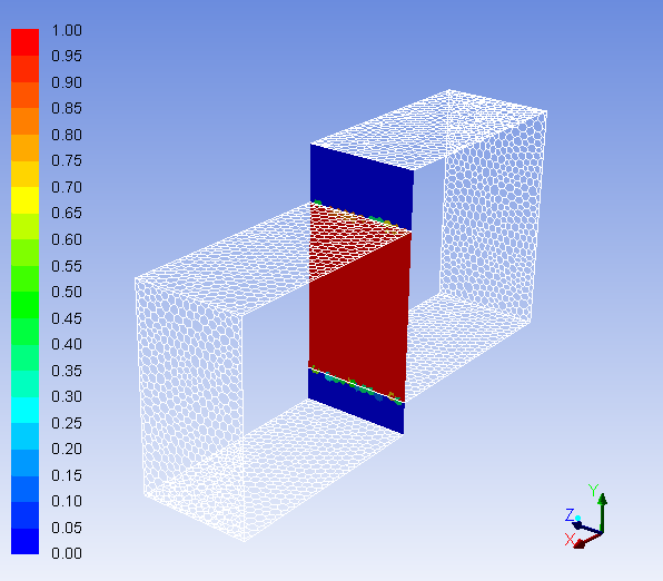
You can visualize the mesh interface(s) you have created by displaying contours of Mesh and Interface Overlap Fraction in the Contours Dialog Box. See Figure 6.50: Contours of Interface Overlap Fraction for an example.
For a one-to-one mesh interface, you also have the option of displaying the intersected zone in the graphics window by using the right-click menu in the outline view tree (under the mesh interface node under Setup / Mesh Interfaces, by default). The intersected zone is of type interior or is a coupled wall (wall or wall shadow) that is generated during the mesh interface creation, and it represents the overlapping area between the two interface zones. In the same way you can also display the non-overlapping zones; note that for non-overlapping zones, the display is approximate at the boundaries of intersected zones, as whole faces will be shown or not shown depending on the location of their centroid.
You can print information in the console about the areas of the zones associated with interfaces either by using the button in the Mesh Interfaces dialog box or by entering the text command
define/mesh-interface/list. The following is the information for a one-to-one mesh interface:>define/mesh-interfaces/list List of Mesh Interface Boundary Zones Interface Boundary: s-1 Area: 1.01046027e-03 Name ID Area Area Percentage ----------------------------------------- ---- ----------------- --------------- intf:01:s-1::r-1 14 8.99861833e-04 89.0546% s-1-non-overlapping 29 1.10513145e-04 10.9369% Interface Boundary: r-1 Area: 1.01029151e-03 Name ID Area Area Percentage ----------------------------------------- ---- ----------------- --------------- intf:01:s-1::r-1 14 8.99861833e-04 89.0695% r-1-non-overlapping 30 1.10303113e-04 10.9179% List of Mesh Interface Area Percentage Name ID Area Area Percentage -------------------------------------- -------- ---------------- ------------------------ intf:01:s-1::r-1 14 8.99861833e-04 89.05% / 89.07%The
Area Percentageis theAreaof a mesh interface / non-overlapping zone divided by the area of an interface boundary. The final line lists theArea Percentagefor both of the interface boundaries, that is,s-1andr-1, respectively.The following is the information for a many-to-many mesh interface:
>define/mesh-interfaces/list

List of Mesh Interfaces


  Interface Name:     intf:01
  Interface Options:  none


       Description                    Name              ID         Area        Area Percentage
---------------------------  -----------------------  -------  --------------  ----------------
      Interface-Zone-Side-1                      s-1       18  1.01046027e-03
      Interface-Zone-Side-2                      r-1        6  1.01029151e-03
Non-Overlapping-Zone-Side-1      s-1-non-overlapping       32  1.10513145e-04          10.9369%
Non-Overlapping-Zone-Side-2      r-1-non-overlapping       33  1.10303113e-04          10.9179%
    Interface-Interior-Zone     intf:01-interior-1-1       31  8.99861833e-04          89.0546%
The
Area Percentageforintf:01-interior-1-1is calculated as the area ofintf:01-interior-1-1divided by the area ofs-1.If you created one-to-one mesh interfaces, you can use the following text command to delete mesh interfaces that have a small area of overlap. You define the area percentage that is used for deletion: if the area that the two zones overlap divided by the area of the zone is less than this value for both zones in any mesh interface, then that mesh interface will be deleted. This can help you easily delete unnecessary or unintentional mesh interfaces.
define→mesh-interfaces→delete-interfaces-with-small-overlap
For dynamic meshes, by default any motion is automatically transferred across a mesh interface when only one side is moving as a result of user-defined or system coupling motion, to ensure that the coupling is maintained on both sides. To change the method by which the displacement of the passive nodes is calculated or to disable this transfer altogether, use the
define/mesh-interfaces/transfer-motion-across-interfaces?text command.With regard to the method by which the motion is transferred, you have two options:
transfer-displacements(the default) interpolates nodal displacement from the active side of the interface to the passive side, and is recommended when there are gaps and/or penetrations in the mesh interface that must be maintained;project-nodesprojects the passive nodes onto the faces of active side, and is recommended when the active side undergoes significant tangential motion (as only the normal displacement is effectively transferred to the passive side in this method). For further details, see Transferring Motion Across a Mesh Interface.
Note: For case files in which the interface was created in Ansys Fluent version 17.2 or earlier,
you may reduce quality issues (such as left-handed faces) and/or convergence problems if
you recreate the interface in version 18.0 or later by entering the following Scheme
command in the console: (recreate-sliding-interfaces).
While it is possible to create every type of many-to-many mesh interface using the manual method, it is only necessary when you want your interface to use the periodic repeats option. If you want your interface to use the periodic option, you can create it manually or by using the Create Periodic dialog box (as described in Creating Periodic Zones and Interfaces). For all other types it is more convenient to use the automatic method (as described in the preceding section), especially when you have many interface zones and/or are unfamiliar with their names / locations.
To manually create a many-to-many mesh interface, you must ensure that the one-to-one interface creation method is disabled and then use the Create/Edit Mesh Interfaces Dialog Box, which is opened by clicking the button in the Mesh Interfaces Dialog Box.
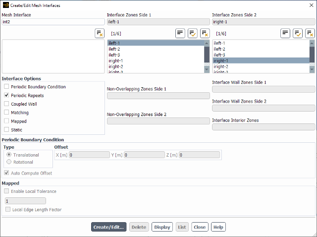
Enter a name for the interface in the Mesh Interface text-entry box.
Specify the interface zones that make up the mesh interface by selecting one or more zones in the Interface Zones Side 1 list and one or more zones in the Interface Zones Side 2 list. Note that you must select only one zone per side if you plan to use the periodic or periodic repeats option.
Enable the desired Interface Options:
Enable Periodic Boundary Condition to create a non-conformal periodic boundary condition interface.
Select either Translational or Rotational as the periodic boundary condition Type to define the type of periodicity.
Retain the enabled default setting of Auto Compute Offset if you want Ansys Fluent to automatically compute the offset. After creating the interface, the offsets will be displayed in these fields. The fields will be uneditable when the Auto Compute Offset is enabled.
Disable Auto Compute Offset if you decide that you do not want Ansys Fluent to find the offset. In this case, you will have to provide the offset coordinates or angle in the required fields, depending on whether Translational or Rotational periodicity is selected.
Important:Auto computation means that the rotational angle or the translational offset will be automatically calculated and used while creating a non-conformal periodic boundary condition interface. However, it still relies on the Rotational Axis Origin and the Rotational Axis Direction that was entered for the cell zone in the cell zone condition dialog box (for example, the Fluid dialog box). Therefore, before proceeding with the creation of the non-conformal periodic boundary condition interface, you have to correctly enter the rotational axis for the corresponding cell zone.
Note that auto computation of the non-conformal periodic boundary condition offset does not mean that the Rotational Axis Origin and Rotational Axis Direction are also detected automatically and updated. It is still your responsibility to set up these values correctly.
When using auto computation for 3D cases, you should ensure that the mesh resolution on the periodic interface zone pairs are similar if both of the following conditions are met: the periodic interface zone pairs are not planar; and they are not connected by at least two face zones that meet at an edge that points from one periodic zone to the other. In such situations, having a similar mesh resolution will produce more precise offset calculations (and subsequently, more accurate solutions). It is recommended that the average mesh size on one boundary should not be more than twice that of the other.
Enable Periodic Repeats when each of the two cell zones has a single pair of conformal or non-conformal periodics adjacent to the interface (see Figure 6.35: Translational Non-Conformal Interface with the Periodic Repeats Option). This option is typically used in conjunction with the sliding mesh model, when simulating the interface between a rotor and stator.
Other options are available, as described in the preceding section. Note that with Periodic Boundary Condition enabled, the Matching option is also enabled by default and no other options are compatible; with Periodic Repeats enabled, only the Coupled Wall option is compatible.
Click to create a new mesh interface. Ansys Fluent will automatically create additional wall and/or interior zones for the interface, which will appear under Non-Overlapping Zones Side 1, Non-Overlapping Zones Side 2, Interface Wall Zones Side 1, Interface Wall Zones Side 2, and Interface Interior Zones.
The buttons at the bottom of the dialog box allow you to take further actions, such as the following:
If you create an incorrect mesh interface, you can select it in the selection list and click the button to delete it. Any additional wall and/or interior zones that were created when the interface was created will also be deleted.
To edit an interface, select it in the selection list and click , and then revise the settings using the Edit Mesh Interfaces Dialog Box that opens.
You can click the button to display interface zones or mesh interfaces in the graphics window. Note that you can only select and display interface zones from Interface Zones Side 1 or Interface Zones Side 2 if no interfaces are selected in the selection list and if the zone in question is not yet assigned to an interface. After an interface is defined, you can select the appropriate mesh interface and click the button to display the zones under Interface Zones Side 1 and Interface Zones Side 2 together. Displaying is particularly useful if you want to check the location of the interface zones prior to setting up a mesh interface.
If you want to easily create many mesh interfaces between boundary zones that do not currently overlap (for example, for a sliding mesh simulation), you can use the Create Mesh Interfaces dialog box. To open this dialog box, you must ensure that the default one-to-one interface creation method is enabled and then click the button in the Mesh Interfaces Dialog Box.
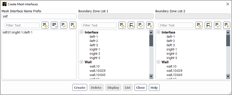
Enter the Mesh Interface Name Prefix you want applied to all of the resulting interfaces.
Select the zones that you want to pair up to make mesh interfaces by selecting one or more zones in the list under Boundary Zone List 1 and one or more zones in the list under Boundary Zone List 2. Note that mesh interfaces will be created for every possible combination between these two lists, regardless of whether the zones in question currently overlap.
Click the button in the Create Mesh Interfaces dialog box to create the mesh interfaces. The resulting mesh interfaces will be displayed in the list under the Mesh Interface Name Prefix field; note that if you select an item in the list, the associated zones will be highlighted in the lists under Boundary Zone List 1 and Boundary Zone List 2. Details about the creation process will be printed in the console, including a list of the resulting mesh interfaces with the area percentage that each boundary zone overlaps the other.
The buttons at the bottom of the Create Mesh Interfaces dialog box allow you to take further actions, such as the following:
If you create an incorrect mesh interface, you can select it in the list under the Mesh Interface Name Prefix field and click the button to delete it. Any additional wall and/or interior zones that were created when the interface was created will also be deleted.
You can click the button to display any of the selected boundary zones and/or mesh interfaces in the graphics window. Note that after you have selected a mesh interface, you can modify what zones are displayed by selecting / deselecting zones under Boundary Zone List 1 and/or Boundary Zone List 2.
You can click the button to print information in the console about the areas of the zones associated with selected mesh interfaces.
Ansys Fluent allows motion to be specified on either side of a mesh interface, and in some instances, can transfer the motion from one side of a mesh interface to the other. When motion is specified on one side of the interface (but not on the other) using either User-Defined Motion or System Coupling Motion, by default Ansys Fluent will automatically interpolate and transfer this motion so that the coupling is maintained on both sides. To disable this transfer or change the method by which the displacement of the nodes on the passive side is calculated, use the following text command:
define → mesh-interfaces
→ transfer-motion-across-interfaces?
When such transfer is disabled, the sides of the mesh interface may separate and/or penetrate over the course of the simulation, which may lead to convergence difficulties and/or an invalid mesh. When it is enabled, you have the following options:
the
transfer-displacementsapproach (default)This approach interpolates nodal displacement from the active side of the interface to the passive side; it uses an inverse-distance weighted interpolation, so that the closer active nodes have more influence. This may be beneficial in situations where gaps and/or penetrations are present at the interface, and they need to be maintained as the simulation progresses. Note that any motion specified tangential to the interface will also be interpolated to the passive side, which can lead to unintended mesh dragging.
the
project-nodesapproachThis approach projects the nodes of the passive side of the interface onto the faces of the active side, in order to maintain conformity. It is beneficial in situations that involve significant tangential motions on the active side of the interface, as only the normal displacement is effectively transferred to the passive side. Note that for mesh interfaces that involve significant gaps or penetration, the
project-nodesapproach may cause the mesh to become invalid.
Note: If you expect the motion to produce large displacements, you should consider applying a mesh update method on the cell zone of the passive side (such as smoothing or remeshing, as described in Dynamic Mesh Update Methods).