


This chapter describes how to create the tetrahedral mesh in the domain. It also describes some of the common problems faced during tetrahedral meshing.
You can use one of the following techniques to generate tetrahedral meshes:
Automatic mesh generation (see Automatically Creating a Tetrahedral Mesh)
Manual mesh generation (see Manually Creating a Tetrahedral Mesh)
A combination of manual and automatic commands (see Initializing the Tetrahedral Mesh, Refining the Tetrahedral Mesh)
If the cells (for example, prisms or pyramids) have already been created in some portion of the computational domain, you need to create a domain encompassing the region to be meshed with tetrahedral cells before starting with the tetrahedral mesh generation. See Using Domains to Group and Mesh Boundary Faces for details. In such cases, all automatic and/or manual meshing actions will apply only to the active domain.
Alternatively, instead of creating a new domain, you can specify the cell zones to be preserved while generating the tetrahedral mesh, before proceeding with the mesh generation. You can use the command /mesh/tet/preserve-cell-zone to specify the cell zones to be preserved.
The > feature contains commands that encapsulate the recommended volume mesh generation strategy. The starting point for this procedure is a valid surface mesh.
The automatic tetrahedral mesh generation process is divided into two fundamental tasks: initialization and refinement.
The automatic initialization procedure includes the following steps:
Merging free nodes.
Deleting unused nodes.
Improving the surface mesh.
Initializing the mesh.
Generating and separating cell regions.
Important: If the mesh fails to initialize, typically this indicates a problem with the surface mesh. In some rare cases, the sliver size (which is automatically computed) may need to be changed. This may happen for domains in which the minimum boundary face size is very small as compared to the domain extent. When changing the sliver size, the rule of thumb is that the specified value should be of the order 1e-12 times the minimum face area.
The automatic refinement procedure includes the following steps:
Sorting the boundary faces by size.
Refining the boundary cells.
Reverse sorting cells by skewness.
Refining the active cell zones.
Swapping cells based on skewness.
Reverse sorting cells by skewness.
Smoothing the mesh.
Removing boundary slivers.
You can select either the advancing front refinement, or the skewness-based refinement of the tetrahedral mesh. The refinement procedure is repeated a number of times.
You can control the number of repetitions for skewness-based refinement by setting the Number of Levels in the Tet Refine Controls dialog box. For each subsequent level of refinement, the cell skewness thresholds are lowered. Additional refinement levels increase the mesh resolution (and the number of cells) and decrease the average cell skewness.
Each refinement level actually consists of two sweeps through the refinement procedure:
One sweep at the appropriate skewness threshold for that particular level of refinement.
Another sweep with a high skewness threshold and a relaxed Min Boundary Closeness set in the Tet Refine Controls dialog box.
This sweep attempts to reduce highly skewed cells in confined regions of the geometry.
Boundary slivers will be removed after the refinement sweeps are complete if the Remove Slivers option is enabled in the Refinement tab of the Tet dialog box.
In some rare cases, it may happen that the first sweep of the first refinement level will never finish because more skewed cells are formed due to refinement, which will be further refined to create more skewed cells, and so on. Such a problem may occur when there is a problem with the boundary mesh, such as rapid mesh transition in small gaps, and so on. You can avoid this problem by using the incremental improvement option for the refinement parameters or by increasing the Min Node Closeness value in the Tet Refine Controls dialog box.
You can select the fast transition option for the refinement parameters in order to generate a mesh with a smaller number of cells. When this option is selected, appropriate refinement parameters will be used to generate fewer cells during meshing. The rate of change of the cell size is increased in order to reduce the number of cells generated. Alternatively, you can specify an appropriate cell sizing option with a sufficiently large value for the growth rate.
Important: Various steps in the automatic meshing process can be added or eliminated using the Tet dialog box. In addition, most aspects of the automatic meshing process can be changed dynamically through the Scheme interface. Contact your support engineer for details.
You can use the > tool to automatically:
Generate a tetrahedral volume mesh starting from a boundary mesh.
Generate a tetrahedral volume mesh in an unmeshed domain of a mesh that contains other cell shapes.
The Auto Mesh tool enables you to generate the tetrahedral volume mesh automatically. When you select Tet in the Volume Fill list and click in the Auto Mesh dialog box:
If the volume mesh does not exist, all the steps listed in Automatic Meshing Procedure for Tetrahedral Meshes will be performed.
If a volume mesh already exists, a Question dialog box will appear, asking if you want to clear the existing mesh. If you click , the volume mesh will be cleared and the active steps in the automatic mesh generation process will be performed. If you click , the operation will be canceled.
Important: You can use the command
/mesh/tet/preserve-cell-zoneto specify the cell zones to be preserved during mesh generation and click Mesh to proceed with the automatic mesh generation.
The Auto Mesh tool enables you to mesh multiple cell zones automatically. This is useful when the mesh has multiple cell zones (for example, the problem requires a fluid zone and one or more solid zones). You can refine the mesh using refinement parameters specific to individual zones, if required. The procedure for meshing multiple cell zones includes the following steps:
Initialize the mesh.
Activate the appropriate zones using the Manage Cell Zones dialog box.
Set the zone-specific refinement parameters and refine the active zones.
If you want to mesh all the zones included in the mesh with the same refinement parameters, modify the Non-Fluid Type in the Tet dialog box.
Important: By default, the Non-Fluid Type is set to dead as the mesh is assumed to consist of a single fluid region and one or more dead regions. The active zone is considered to be the fluid zone and only this fluid zone will be considered for refinement during the automatic meshing process.
When the Non-Fluid Type is set to a type other than dead (for example, solid), all the zones will be active after the initialization is complete. Hence, all the zones will be considered for refinement. If required, you can change the zone type using the Manage Cell Zones dialog box.
Select the appropriate type from the Non-Fluid Type drop-down list in the Tet Zones group box in the Tet dialog box before initializing the mesh.
Note: For zone-based meshing, if any cell zone has at least one boundary zone type as inlet, it will automatically be set to fluid type. For object based meshing, volume region type is used to determine the cell zone type.
The Auto Mesh tool can also create prisms and pyramids automatically, allowing automatic generation of hybrid meshes.
If a mix of surface mesh types (quadrilateral and triangular) is present in the domain, pyramid cell zones will be created on the quadrilateral boundary faces before meshing the tetrahedral domain.
If prism growth parameters have been attached to a boundary zone (using the Prisms dialog box), the prism layers will be automatically extruded before meshing the tetrahedral domain.
When pyramids or prisms are generated using the automatic mesh generation feature, the intermediate boundary zones will be merged automatically after the tetrahedral mesh generation is complete. This enhancement avoids the creation of additional boundary zones such as prism-side and pyramid-cap (see Zones Created During Prism Generation and Zones Created During Pyramid Generation).
You can transition from quad to tri faces using the Non Conformals option. This option is useful when you want to avoid pyramids on quad faces when growing prisms from a boundary. For mixed surface mesh types (quadrilateral and triangular), you can select Non Conformal in the Quad Tet Transition list in the Auto Mesh dialog box. The surfaces containing quad faces will be copied and triangulated, keeping the original faces intact. The free nodes of the triangulated surface will then be merged with the nodes of the original surface mesh and both the surfaces will be converted to interface type.
Examine the following after completing the automatic mesh generation process:
The mesh size with the Report Mesh Size dialog box (see also Determining Mesh Statistics).
The prism layer cell quality distribution (see Determining Boundary Cell Quality), if appropriate.
The tet cell quality reports (see also Determining Volume Mesh Quality).
It is typically possible to reduce the maximum skewness to the range 0.8–0.9. Skewness values higher than 0.9 are typically obtained due to constraints imposed by the surface meshes. If you still have highly skewed cells apply additional swapping and smoothing to improve the quality (see Smoothing Nodes and Swapping). To increase the density of the mesh locally, use refinement regions (see Using Local Refinement Regions).
Warning: Do not over-refine the mesh. The volume mesh produced should be of sufficient density to resolve the shape of the geometry. The mesh can be improved more effectively using the solution-adaptive mesh capability provided in the solution mode in Fluent.
In addition to the Auto Mesh tool, you can control the tetrahedral mesh generation process by modifying parameters at each step. The basic operations are described here, and the methods for modifying the associated parameters are described in Initializing the Tetrahedral Mesh and Refining the Tetrahedral Mesh.
The basic components of the manual meshing process are examining and repairing the surface mesh, creating an initial mesh, refining the mesh, and improving the mesh.
The following steps describe the recommended meshing procedure.
Step 1: Examining the Surface Mesh
The first step in the mesh generation process is to examine the validity and quality of the surface mesh. The recommended approach includes the following steps:
Checking for free and isolated nodes (see Free and Isolated Nodes).
Checking and improving the surface mesh quality (see Improving Boundary Surfaces).
Visually examining the surface mesh for free, multiply-connected, skewed, and/or close-proximity faces (see Displaying the Mesh).
Making local repairs if required (see Modifying the Boundary Mesh).
After obtaining a valid, (ideally) high-quality surface mesh, you can proceed to create the volume mesh.
Step 2: Creating the Initial Mesh
The first step in generating the volume mesh is creating the initial mesh. This process first creates a pre-meshed box encompassing the entire geometry, and then sequentially introduces each boundary node into the mesh. As the nodes of a boundary face are inserted into the mesh, any necessary mesh modifications needed to insert the face are performed, effectively inserting both boundary nodes and faces into the mesh simultaneously. For more information see Initializing the Tetrahedral Mesh.
Activating Multiple Zones (for Multi-zone Meshes Only)
If the mesh has multiple regions (for example, the problem requires a fluid zone and one or more solid zones), you can refine the mesh using refinement parameters specific to individual zones, if required. The procedure for meshing multiple cell zones includes the following steps:
Initialize the mesh.
Activate the appropriate zones using the Manage Cell Zones dialog box.
Set the zone-specific refinement parameters and refine the active zones.
If you want to mesh all the zones included in the mesh with the same refinement parameters, modify the Non-Fluid Type in the Tet dialog box.
Select the appropriate type from the Non-Fluid Type drop-down list in the Tet Zones group box in the Tet dialog box.
Important: By default, the Non-Fluid Type is set to dead as the mesh is assumed to consist of a single fluid region and one or more dead regions. The active zone is considered to be the fluid zone and only this fluid zone will be considered for refinement during the automatic meshing process.
When the Non-Fluid Type is set to a type other than dead (for example, solid), all the zones will be active after the initialization is complete. Hence, all the zones will be considered for refinement. If required, you can change the zone type using the Manage Cell Zones dialog box.
Note: For zone-based meshing, if any cell zone has at least one boundary zone type as inlet, it will automatically be set to fluid type. For object based meshing, volume region type is used to determine the cell zone type.
Step 3: Refining the Mesh
You will refine the initial mesh by adding cells at the boundary and in the interior. The refinement methods available are the skewness-based method and the advancing front method. You can also define local refinement regions using the Tet Refinement Region dialog box. You can modify the parameters in the Refinement tab of the Tet dialog box and select additional refinement options for skewness-based refinement in the Tet Refine Controls dialog box, if required.
Step 4: Improving the Mesh
You can improve the skewness by smoothing, swapping, and refining the mesh further to improve the quality of the volume mesh. At any point in the mesh generation process, you can compute and plot the cell skewness distribution using the Cell Distribution dialog box. The number of cells in the specified range in each of the regularly spaced partitions is displayed in a histogram format. The x axis shows either the size or the quality and the y axis gives the number of cells or the percentage of the total. This will give you an idea of the improvement required. It is typically possible to reduce skewness to 0.8–0.85 (for simple geometries) or 0.9–0.95 (for more complex geometries).
Note: If you have used domains to generate the mesh or group zones for reporting (as described in Using Domains to Group and Mesh Boundary Faces), you can report the cell distribution only for those cell zones that are in the active domain.
Step 4a: Swapping and Smoothing without Refining
Swapping and smoothing improve the mesh by manipulating the nodes and faces without increasing the total number of cells. Refinement, on the other hand, improves the mesh by adding nodes, which typically increases the number of cells. To get the best possible mesh with the minimum number of cells, perform only smoothing and swapping before refining the mesh any further.
Smoothing repositions interior nodes to lower the maximum skewness of the mesh. For swapping, given n+2 nodes in dimension n, there are at most two triangulations of the nodes depending on the configuration of the nodes. In cases where two triangulations exist, the two alternatives are examined, and the one that has the lowest maximum skewness is selected. Smoothing and swapping are automatically performed to improve the mesh when the Improve Mesh option is enabled in the Refinement tab of the Tet dialog box.
Refer to Smoothing Nodes and Swapping for details on improving the mesh by swapping and smoothing.
You can further refine the cells in the active zones by changing parameters such as Max Cell Volume, and Max Cell Skew and Max Boundary Cell Skew (available only for skewness-based refinement).
Important: Changing mesh size controls other than Max Cell Volume will have no effect on a mesh that has already been refined. Alternately, use local refinement regions. Refer to Using Local Refinement Regions for details.
Refining with skewness parameters reduced to values less than 0.5 will rarely improve the mesh and will be very time-consuming.
Important: Do not over-refine the mesh, the volume mesh produced should be of sufficient density to resolve the shape and any intuitive flow features (for example, wall boundary layers). Additional resolution can be more effectively produced using the solution-adaptive mesh capability provided in the solution mode in Fluent.
At this step you will have an acceptable mesh for most geometries.
Step 4c: Boundary Slivers and Other Sources of Lingering High Skewness
When viewing the cell distribution plot, if you find that there are a few cells with very high skewness, check to see where they are located (that is, on the boundary or in the interior). To do so, use the Report Boundary Cell Limits dialog box. When using that dialog box, note that if you have used domains to generate the mesh or group zones for reporting (as described in Using Domains to Group and Mesh Boundary Faces), the report will apply only to the active domain.
Refer to Removing Slivers from a Tetrahedral Mesh and Moving Nodes for details on removing slivers and other mesh improvement options.
You can initialize and refine the tetrahedral mesh in a single step by clicking the button in the Tet dialog box after setting the appropriate parameters in the Initialization and Refinement tabs. Alternatively, you can set the appropriate parameters in the Initialization tab and click the button to create the initial mesh. You can then refine the initial mesh by setting the appropriate parameters in the Refinement tab and clicking the button.
If you need to refine a particular region, you can define the region to be refined using the Tet Refinement Region dialog box.
The first step in the volume mesh generation process is initialization. The initial mesh consists of the nodes and triangles of the boundary surface mesh. For some geometries, it is not possible to create a tetrahedral mesh from the boundary nodes alone. In such cases, a small number of nodes are automatically added in the interior of the domain. Interior nodes may also have to be added to resolve numerical problems associated with the Delaunay criterion.
You can use > to initialize the mesh using the options available in the Initialization tab of the Tet dialog box.
Select the appropriate option from the Non-Fluid Type drop-down list. Enable Delete Dead Zones, if required.
When the initial mesh is generated, all the cells are grouped into contiguous zones separated by boundaries. The mesh is considered to contain a single fluid zone and one or more dead regions. The zone just inside the outer boundary is set to be active and is labeled a fluid zone. All other non-fluid zones will be inactive. Only active zones will be considered for refinement during the mesh generation process.
Note: For zone-based meshing, if any cell zone has at least one boundary zone type as inlet, it will automatically be set to fluid type. For object based meshing, volume region type is used to determine the cell zone type.
You can refine different groups of zones using different refinement parameters for each group by toggling the zones between active and inactive. If however, you need to use the same refinement parameters for all the zones, you can change the specification of Non-Fluid Type to a type other than dead (for example, solid). When the Non-Fluid Type is set to a type other than dead, all the zones will be activated after initialization. Hence, you can set the appropriate refinement parameters without setting all the zones to be active.
Note: If you have enabled the Delete Dead Zones option and subsequently change the region type from dead to either fluid or solid, then while generating the volume mesh using the Auto Mesh tool, the regions marked as dead are not filled with the volume mesh and are disconnected from the regions that are being volume meshed. These regions can later be reconnected after volume meshing by merging the relevant nodes.
Specify additional initialization parameters, if required. These parameters are available in the Tet Init Controls dialog box. Click the Controls... button to open the Tet Init Controls dialog box.
Click to initialize the mesh.
A Working dialog box will appear, informing you that the initialization is in progress. Click the button in the Working dialog box to abort the mesh initialization process. Canceling the initialization will leave the mesh incomplete.
If you try to initialize the mesh after canceling an initial attempt, a dialog box will ask if it is OK to clear the incomplete mesh.
After you approve, the initialization process will begin again.
If you try to initialize the mesh when duplicate nodes exist, the initialization will fail. You must clear the mesh and merge the duplicate nodes before attempting the initialization again.
If you try to initialize the mesh when a volume mesh already exists, a Question dialog box will appear, asking if you want to clear the existing mesh. If you click Yes, the volume mesh will be cleared and then the mesh will be initialized. If you click No, the operation will be canceled.
If you need to preserve the existing mesh during the meshing process, use the command
/mesh/tet/preserve-cell-zoneto specify the cell zones to be preserved and click the Init button to proceed with the initialization.If the initial mesh generation fails, check the validity of the surface mesh. In some rare cases, you may need to change the sliver size parameter (by using the Tet dialog box).
Refer to Common Tetrahedral Meshing Problems for more information on meshing problems.
After initializing the mesh, you can improve the quality and density of the mesh using global and local refinement. Global refinement enables you to refine all cells in the active zones, while local refinement enables you to refine cells within a specified region.
In most applications, you will use only global refinement to create an acceptable discretization of the volume. Local refinement is used to modify the grading away from boundaries or increase the resolution of an interior region of the mesh. You need to define and activate the regions to be refined before proceeding.
The refinement process includes a series of sweeps through a sequence of sorting, refining, reverse sorting, and swapping and smoothing of the cells. You can specify the number of refinement levels to be performed for skewness-based refinement. Each refinement level consists of two iterations through the refinement procedure. For each subsequent level of refinement, the cell skewness thresholds are lowered. Additional refinement levels will increase the mesh resolution (and the number of cells) and decrease the average cell skewness. The preset refinement control parameters are available in the Tet Refine Controls dialog box. Alternatively, you can select the advancing front refinement method.
Specify whether the mesh has to be improved or if the slivers have to be removed during refinement.
The Improve Mesh option performs additional smoothing and swapping with lowered skewness thresholds, attempting to improve the average skewness of the mesh.
The Remove Slivers option attempts to lower the maximum skewness by improving highly skewed (sliver) cells. There are two approaches for sliver removal: fast and aggressive. Both methods use the same controls and give similar results for good quality surface meshes. In case of poor surface meshes (meshes with large size difference between neighboring elements, narrow gaps with widely varying mesh sizes on either side of the gap, and so on), the aggressive method will typically succeed in improving the mesh to a greater extent, but it may be slower than the default fast method.
The aggressive method corresponds to the Improve option in the Tet Improve dialog box.
The boundary mesh is fixed during the mesh improvement and sliver removal operations.
Refinement Controls
The refinement controls for the skewness method are available in the Tet Refine Controls dialog box. Click the Controls... button in the Refinement tab of the Tet dialog box to open the Tet Refine Controls dialog box.
Note: Skewness-based refinement controls are no longer supported and will be removed in a future release.
The refinement controls for the advancing front method are available in the /mesh/tet/controls/adv-front-method menu. The /mesh/tet/controls/adv-front-method/skew-improve/target? command is important as it enables you to enable targeted skewness-based refinement for the advancing front method. The refinement process will attempt to reach the targeted skewness (specified by the command /mesh/tet/controls/adv-front-method/skew-improve/target-skew). Though the default values work well in most situations, it may be advantageous to increase the target-skew value in some cases (for example, cases where a combination of a poor surface mesh and narrow gaps will result in poor cells in the mesh) to increase the meshing speed.
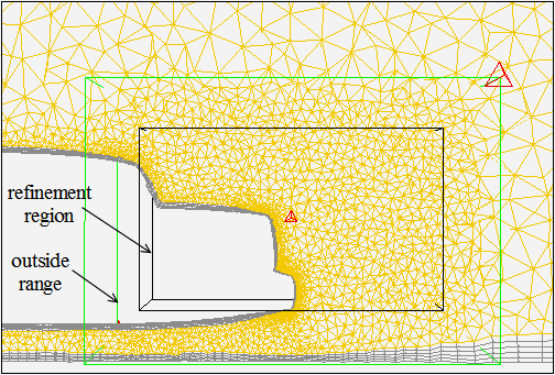
A refinement region limits refinement to specific cells inside the domain. When you use the Refine option in the Tet Refinement Region dialog box, the cells within the activated regions are refined. The primary use of refinement regions is to reduce the cell size in the region to less than it would be normally. Currently, the only possible region shape is a box, which can be oriented as required.
The region is defined by an x, y, and z range and its orientation about the x, y, and z axes. Any cell within the region or that intersects the region will be subjected to the refinement criteria. You can control the concentration of interior nodes by specifying the maximum cell volume in the refinement region. It is possible to save different values for the Maximum Cell Volume when you save each region. You can also specify an outer region with the required volume growth to have a smooth transition between the original and the refined cells.
Note: In addition to the use of refinement regions for refinement during the mesh generation process, they can also be used as a postprocessing tool to refine a region of an existing mesh.
You can create multiple regions that overlap each other and the geometry. To create additional regions, you can copy an existing region and then modify the parameters as required. The default region includes the entire geometry.
Figure 7.105: Local Refinement Region for the Tetrahedral Mesh shows the refinement region and outer region. The maximum cell size for the refinement and outer regions is displayed based on the maximum cell volume and outside volume growth specified. For information on refining triangular boundary faces in anticipation of local refinement, refer to Refining the Boundary Mesh.
You can use > to refine the mesh using the options available in the Refinement tab of the Tet dialog box.
Select the appropriate refinement method from the Refine Method drop-down list.
Enable the appropriate options in the Options group box.
Specify an appropriate value for Max Cell Volume.
Select the appropriate option from the Cell Sizing drop-down list.
Ensure that the cells in the interior are not larger than the size required by selecting the appropriate option in the Cell Sizing list. The following options are available:
- geometric
specifies that the cell size in the interior of the domain is obtained by a geometric growth from the closest boundary according to the growth rate specified.
- size-field
specifies that the cell size is determined based on the current size-field.
Note: Additional cell sizing options (none (for skewness-based refinement only) and linear) are available only via text commands. See the Text Command List for details.
Modify the refinement control parameters, if required.
For the advancing front method, use the commands available in the
/mesh/tet/controls/adv-front-methodmenu. You can also specify the targeted skewness for the refinement process (see Refinement Controls for details).
To refine specific regions of the mesh, click the Local Regions... button to open the Tet Refinement Region dialog box. Define the refinement regions and activate them. The number of activated regions will be reported in the Message field in the Refinement tab of the Tet dialog box.
Click Refine to refine the mesh.
Most problems with the mesh generation process become manifest in the failure to generate an initial mesh. There are two sources of such problems:
An invalid surface mesh
Incorrect sliver size specified
Some of the common problems and suggestions for checking and fixing the mesh are described in this section.
To look at the nodes and faces that have not been meshed, enable Unmeshed in the Display Grid dialog box.
Duplicate Nodes or Faces
Some codes create multiple copies of the same node where two boundary curves or surfaces meet, resulting in a connectivity problem. This problem can be detected by reporting the number of free nodes or by drawing the free edges. If the geometry does not contain infinitely thin walls then there should not be any free nodes or edges. You can remove duplicate nodes using the /boundary/delete-duplicate-nodes command.
The presence of duplicate faces can be detected in one of two ways:
If the nodes of the duplicate faces are not shared by the non-duplicate faces, the duplicate faces may have free edges that can be displayed.
If the nodes are not distinct or have been merged, there will be multiply-connected edges.
Note: Duplicate faces can be handled, it is not necessary to remove them.
Extra Nodes or Faces
Nodes that are not used by any face are called unused nodes. The unused nodes can easily be found and deleted using the Merge Boundary Nodes dialog box, if those nodes are not required. However, there are cases where these additional nodes may be useful (see Inserting Isolated Nodes into a Tet Mesh). Extra faces can be identified and removed using the method described for duplicate faces.
To merge nodes that are not on a free edge, in the Merge Boundary Nodes dialog box disable Only Free Nodes in the Compare... or With... group box or in both group boxes. For example, if you read a hybrid mesh containing hexahedral cells (and quadrilateral boundary faces) and triangular boundary faces, there may be some duplicate nodes on adjacent quadrilateral and triangular boundary zones. To merge them, compare free nodes on both zones with all nodes on both zones (that is, select both zones in the Compare... and With... group boxes, and disable Only Free Nodes in one of them).
Intersecting Faces
If there are intersecting faces in the mesh, you will not be able to generate a mesh until the problem faces are removed. Most intersecting faces can be located using the /boundary/mark-face-intersection command. If intersecting boundary faces are encountered during initialization, a message will be displayed.
After the meshing fails, the unmeshed faces can be drawn to see the problem area. Usually, because the intersecting face will have been meshed, it will not be drawn and some additional sleuthing will be required. Draw all the faces near the unmeshed faces by setting display bounds (by using the Display Grid dialog box). Click the button in the Intersect Boundary Zones dialog box to highlight the face intersection. Alternatively, you can use the command /boundary/mark-face-intersection to highlight the face intersection. When you set the Feature Angle, note that this specifies the minimum angle between the feature edges that should be preserved during retriangulation. All the edges in the zone having feature angle greater than the specified Feature Angle are retained. This option is useful for preserving the shape of the intersecting boundary zones. A value in the range of 10–50° is recommended; a large value may distort the shape of the intersecting boundary zones.
Poor Boundary Node Distribution
Some meshing problems can be caused by a poor quality surface mesh. The surface mesh may have highly skewed faces, or two or more boundaries in close proximity may have very different face sizes. In the latter case, the boundaries can be connected (for example, in a corner) or completely separate. Either way, the boundary mesh cannot be created without considering the impact of other nearby boundaries.
If the gap between two boundaries is D, the largest edge on a face should not exceed D. The mesh quality is extremely important when a coarse mesh is required in a small gap.
Non-Closed Boundaries
You can generate an initial mesh even if there is a hole in a boundary either due to missing faces or a gap between two zones. In this case, instead of having two separate zones on opposite sides of the boundary, you will have just one combined zone. This situation is evident because you will have very few zones.
If the hole is in the outer boundary, the cells outside the boundary will be combined with the cells inside, resulting in an error. The edges around the hole will be marked as free edges and therefore can be displayed.
If the problem is caused by a small gap between boundaries and the duplicate nodes have already been merged, increase the tolerance and perform additional merging.
The following command can be used to detect holes in the geometry by tracing the path between the two specified cells:
/mesh/tet/trace-path-between-cells
A path between the selected cells will be highlighted.
Interior Node Near Boundary
During refinement, a node may be placed too close to a boundary face, resulting in a highly skewed cell. You can detect this situation by displaying the highly skewed cells. You can then smooth the mesh to eliminate the problem.
If the interior node is constrained by the boundary faces, increase the Min Boundary Closeness (in the Tet Refine Controls dialog box) and regenerate the mesh.