


Since the Ansys Fluent solver is face based, it supports polyhedral cells. The advantages that polyhedral meshes have shown over some of the tetrahedral or hybrid meshes is the lower overall cell count, almost 3-5 times lower for unstructured meshes than the original cell count. Currently, there are three options in Ansys Fluent that allow you to convert your non-polyhedral cells to a polyhedra:
Converting the entire domain into polyhedral cells (applicable only for meshes that contain tetrahedral and/or wedge cells).
Converting skewed tetrahedral cells to polyhedral cells.
Converting cells with hanging nodes / edges to polyhedral cells.
Information about polyhedral mesh conversion is provided in the following sections:
Conversion of a mesh to polyhedra only applies to 3D meshes that contain tetrahedral and/or wedge cells.
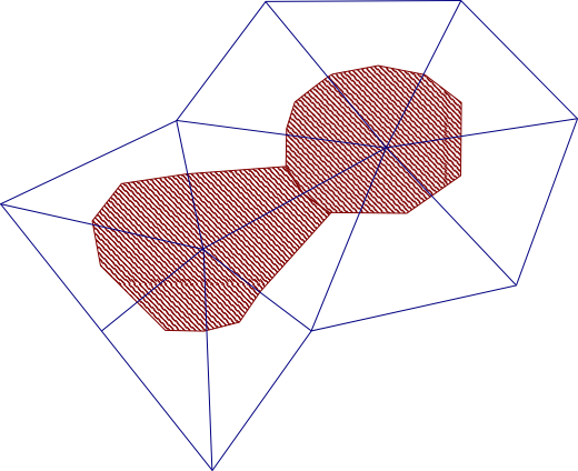
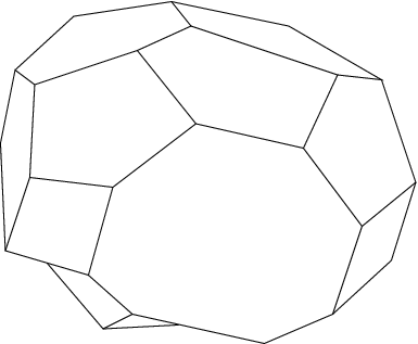
To begin the conversion process, Ansys Fluent automatically decomposes each non-hexahedral cell into multiple sub-volumes called “duals” (the shaded regions seen in the 2D example in Figure 6.84: Connection of Edge Centroids with Face Centroids). Each dual is associated with one of the original nodes of the cell. These duals are then agglomerated into polyhedral cells around the original nodes. Therefore, the collection of duals from all cells sharing a particular node makes up each polyhedral cell (see Figure 6.85: A Polyhedral Cell). The node that is now within the polyhedral cell is no longer needed and is removed.
To better understand how duals are formed, you can consider the straightforward case of a tetrahedral mesh. Each of the cells are decomposed in the following manner: first, new edges are created on each face between the face centroid and the centroids of the edges of that face. Then, new faces are created within the cell by connecting the cell centroid to the new edges on each face. These interior faces establish the boundaries between the duals of a cell, and divide the cell into 4 sub-volumes. These dividing faces may be adjusted and merged with neighboring faces during the agglomeration process, in order to minimize the number of faces on the resultant polyhedral cell.
Note: By default, Ansys Fluent checks the aspect ratio of boundary layer cells and if the aspect
ratios are high, Ansys Fluent asks whether you want to preserve cells at the boundary layer
(which could be useful for keeping cell counts low when retaining boundary features). You
can override this default with the text command:
mesh/polyhedra/options/preserve-boundary-layer? (for additional
information about these options, see
mesh/
in the Fluent Text Command List).
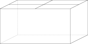
Important: Hexahedral cells are not converted to polyhedra when the domain is converted, except when they border non-hexahedral cells. When the neighboring cell is reconfigured as polyhedra, the shared face of the hexahedral cell is decomposed into multiple faces as well, resulting in a polyhedral cell. In such a case the shape of the original hexahedral cell is preserved (that is the overall dimensions of the cell stay the same), but the converted cell has more than the original 6 faces (see Figure 6.86: A Converted Polyhedral Cell with Preserved Hexahedral Cell Shape).
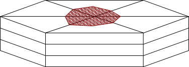
Conversion proceeds in a slightly different manner in boundary layers that are modeled using thin wedge cells. These cells are decomposed in the plane of the boundary surface, but not in the direction normal to the surface. The resulting polyhedra will therefore preserve the thickness of the original wedge cells (Figure 6.87: Treatment of Wedge Boundary Layers). In most cases, the cell count in the new polyhedral boundary layer will be lower than the original boundary layer.
To convert the entire domain of your mesh, click in the Domain ribbon tab (Mesh group box).
![]() Domain → Mesh
→ Make Polyhedra
Domain → Mesh
→ Make Polyhedra
The following is an example of the resulting message printed in the console:
 Setup conversion to polyhedra.
 Converting domain to polyhedra...

      Creating polyhedra zones.
      Processing face zones...........
      Processing cell zones...
      Building polyhedra mesh...................
      Optimizing polyhedra mesh.....
>> Reordering domain using Reverse Cuthill-McKee method:
    zones, cells, faces, done.
 Bandwidth reduction = 1796/247 = 7.27
 Done.
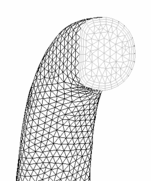
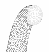
Figure 6.88: The Original Tetrahedral Mesh, the original tetrahedral mesh of a section of a manifold, is compared to Figure 6.89: The Converted Polyhedral Mesh, which is the resulting mesh after the entire domain is converted to a polyhedra.
Note that by default, the surfaces (that is, manifold zones of type interior) will be lost during the conversion to polyhedra. If you would like to preserve any of these zones (in order to utilize them for postprocessing, for example), use the following text command prior to the conversion:
mesh → polyhedra →
options →
preserve-interior-zones
You will be prompted to enter a string of characters, and only those interior surfaces with a name that includes the string you specify will be preserved.
In parallel, a new partitioning will be stored after the conversion, but by default
these new partitions will not be made active (that is, migrated to the compute-nodes) as
this requires significant additional memory. The new partitions will be saved with the case
file and used automatically when it is opened in a new Fluent session; it is recommended
that you then manually reorder the domain prior to calculating (using the
mesh/reorder/reorder-domain text command). If you want to use the
new partitions in the current Fluent session, you should first ensure that no more than
half of the available memory of this system is currently used, and then you can manually
migrate the partitions (using the
parallel/partition/use-stored-partitions text command) and
reorder. If you know prior to conversion that you will want to calculate a solution in the
same session (and you have sufficient memory), you can enable the following text command, so
that the migration and reordering is performed automatically as part of the
conversion:
mesh → polyhedra →
options → migrate-and-reorder?
Some limitations you will find with polyhedral meshes that you generally do not experience with other cell types include:
Meshes that already contain polyhedral cells cannot be converted.
Meshes with hanging nodes / edges will not be converted. This includes meshes that have undergone hanging node adaption (see Hanging Node Adaption in the Theory Guide), as well as CutCell meshes and hexcore meshes (generated when using the Hex Core meshing scheme in GAMBIT or the Hexcore menu option in the meshing mode of Fluent) which you have read after disabling the automatic conversion of hanging nodes / edges (see Converting Cells with Hanging Nodes / Edges to Polyhedra for details).
The following mesh manipulation tools are not available for polyhedral meshes:
the
mesh/modify-zones/extrude-face-zone-deltatext commandthe
mesh/modify-zones/extrude-face-zone-paratext commandskewness smoothing
swapping
Meshes in which the domain has been converted to polyhedral cells are not eligible for adaption with the hanging node method, though they can be refined with the default polyhedral unstructured mesh adaption (PUMA) method. For more information about adaption, see Adapting the Mesh.
A mesh that is composed entirely of polyhedral cells has limitations when used in a dynamic mesh problem: it cannot undergo remeshing. Smoothing is allowed for polyhedral cells, and radial basis function smoothing is the recommended method (see Radial Basis Function Smoothing for details). The linearly elastic solid smoothing method is not compatible with polyhedral cells.
Since polyhedral meshes can have a much higher ratio of nodes to cells then tet or hex meshes, the use of the node-based gradient method may result in a significant increase in memory consumption compared with other gradient methods.
Another method of cell agglomeration is the skewness-based cluster approach. This type of conversion is designed to convert only part of the domain. The objective is to convert only skewed tetrahedral cells above a specified cell equivolume skewness threshold into polyhedra. By converting the highly skewed tetrahedral cells, the quality of the mesh can be improved significantly.
A different algorithm is used for local conversion. This algorithm evaluates each highly skewed tetrahedral cell and all of the surrounding cells, to select an edge on the highly skewed cell that best matches criteria for cell agglomeration. Then all of the cells that share this edge are combined into a polyhedral cell. During the process, the data is interpolated from the original cells to the resultant polyhedra.
There are certain limitations with this type of conversion:
The following mesh manipulation tools are not available on polyhedral meshes:
the
mesh/modify-zones/extrude-face-zone-deltatext commandthe
mesh/modify-zones/extrude-face-zone-paratext commandskewness smoothing
swapping will not affect polyhedral cells
The polyhedral cells that result from the conversion are not eligible for adaption with the hanging node method, though they can be refined with the default polyhedral unstructured mesh adaption (PUMA) method. For more information about adaption, see Adapting the Mesh.
Only tetrahedral cells are converted, as all other cells are skipped.
Meshes with hanging nodes / edges will not be converted. This includes meshes that have undergone hanging node adaption (see Hanging Node Adaption in the Theory Guide), as well as CutCell meshes and hexcore meshes (generated when using the Hex Core meshing scheme in GAMBIT or the Hexcore menu option in the meshing mode of Fluent) which you have read after disabling the automatic conversion of hanging nodes / edges (see Converting Cells with Hanging Nodes / Edges to Polyhedra for details). Note that if the mesh is a CutCell / hexcore mesh in which the transitional cells have been converted to polyhedra, then it does not have hanging nodes / edges and can therefore be converted.
Note the following with regard to the polyhedral cells that result from this conversion and the update methods available for dynamic mesh problems:
None of the remeshing methods will modify polyhedral cells.
Smoothing is allowed for polyhedral cells, and radial basis function smoothing is the recommended method (see Radial Basis Function Smoothing for details). The linearly elastic solid smoothing method is not compatible with polyhedral cells.
3D meshes that contain hanging nodes or hanging edges are by
default converted when the file is read, so that the cells adjacent to the hanging nodes /
edges become polyhedra. Each cell that is converted will retain the same overall dimensions,
but the number of faces associated with the cell may increase (see Figure 6.86: A Converted Polyhedral Cell with Preserved Hexahedral Cell Shape for an example). Such a conversion may be helpful for
CutCell meshes, as well as hexcore meshes (generated when using the Hex
Core meshing scheme in GAMBIT or the Hexcore menu option
in the meshing mode of Fluent), and may prevent errors associated with interior walls (see
Removing Hanging Nodes / Edges). You can opt to disable this conversion by using the
following text command prior to reading: file/convert-hanging-nodes-during-read?
no.
Ansys Fluent also provides a text command that allows you to convert 3D cells that have hanging nodes / edges into polyhedra after reading. For example, you may want to convert the cells with hanging nodes in a mesh that has undergone hanging node adaption (see Adapting the Mesh); note that you want to be sure that no further refinement / coarsening of the mesh will be necessary. To convert the cells with hanging nodes / edges after reading, use the following text command:
mesh → polyhedra →
convert-hanging-nodes
There are certain limitations with this type of conversion:
The following mesh manipulation tools are not available on polyhedral meshes:
the
mesh/modify-zones/extrude-face-zone-deltatext commandthe
mesh/modify-zones/extrude-face-zone-paratext commandskewness smoothing
swapping will not affect polyhedral cells
The polyhedral cells that result from the conversion are not eligible for adaption with the hanging node method, though they can be refined with the default polyhedral unstructured mesh adaption (PUMA) method. For more information about adaption, see Adapting the Mesh.
Note the following with regard to the polyhedral cells that result from this conversion and the update methods available for dynamic mesh problems:
None of the remeshing methods will modify polyhedral cells.
Smoothing is allowed for polyhedral cells, and radial basis function smoothing is the recommended method (see Radial Basis Function Smoothing for details). The linearly elastic solid smoothing method is not compatible with polyhedral cells.