Since Ansys Fluent can handle a number of different mesh topologies, there are many sources from which you can obtain a mesh to be used in your simulation. You can generate a mesh using Ansys Meshing, the meshing mode of Fluent, Fluent Meshing, GAMBIT, GeoMesh, ICEM CFD, NASTRAN, ARIES, CFX, or other preprocessors. You can also use the mesh contained in a Fluent/UNS or RAMPANT. You can also prepare multiple mesh files and combine them to create a single mesh.
- 6.3.1. Ansys Meshing Mesh Files
- 6.3.2. Fluent Meshing Mode Mesh Files
- 6.3.3. Fluent Meshing Mesh Files
- 6.3.4. GAMBIT Mesh Files
- 6.3.5. GeoMesh Mesh Files
- 6.3.6. NASTRAN Files
- 6.3.7. CFX Files
- 6.3.8. Using the fe2ram Filter to Convert Files
- 6.3.9. Removing Hanging Nodes / Edges
- 6.3.10. Fluent/UNS and RAMPANT Case Files
- 6.3.11. Ansys FIDAP Neutral Files
- 6.3.12. Reading Multiple Mesh/Case/Data Files
- 6.3.13. Reading Surface Mesh Files
You can use Ansys Meshing to create your mesh. Follow the meshing procedure and export to the Ansys Fluent mesh format (see Fluent Mesh Export in the Ansys Meshing User’s Guide for details). To import the mesh into Fluent, use the File/Read/Mesh... ribbon tab item (as described in Reading Mesh Files).
You can use the meshing mode of Fluent (which was previously a stand-alone program named Fluent Meshing) to create 3D unstructured triangular/tetrahedral meshes from boundary or surface meshes. Switch to meshing mode and then follow the meshing procedure described in the Fluent Meshing section of the User’s Guide. You can save your mesh using the File/Write/Mesh... menu item.
Then switch to the solution mode to set up the case file for the transferred mesh, or import the saved mesh into a new Fluent session using the File/Read/Mesh... ribbon tab item (as described in Reading Mesh Files).
For information about switching between meshing and solution modes, see Switching Between Meshing and Solution Modes in the Getting Started part of this manual.
Prior to version 14.5, Fluent Meshing was a stand-alone product that was used to create 3D unstructured triangular/tetrahedral meshes from boundary or surface meshes. Fluent Meshing has been integrated as the Fluent meshing mode. To import meshes created by Fluent Meshing into Fluent, use the File/Read/Mesh... ribbon tab item (as described in Reading Mesh Files).
You can use GAMBIT to create 2D and 3D structured/unstructured/hybrid meshes. To create any of these meshes for Ansys Fluent, follow the procedure described in the GAMBIT Modeling Guide, and export your mesh in Fluent 5/6 format. All such meshes can be imported directly into Ansys Fluent using the File/Read/Mesh... ribbon tab item, as described in Reading Mesh Files.
You can use GeoMesh to create complete 2D quadrilateral or triangular meshes, 3D hexahedral meshes, and triangular surface meshes for 3D tetrahedral meshes. To create any of these meshes for Ansys Fluent, follow the procedure described in the GeoMesh User's Guide.
To complete the generation of a 3D tetrahedral mesh, read the surface mesh into the meshing mode of Fluent and generate the volume mesh there (see the Fluent Meshing section of the User’s Guide for details). All other meshes can be read directly into the solution mode of Fluent. Use the File/Read/Mesh... ribbon tab item to read the mesh files, as described in Reading Mesh Files.
There are three different ways in which you can import a NASTRAN file into Ansys Fluent:
You can generate a NASTRAN surface or volume mesh containing triangular, quadrilateral, tetrahedral, wedge, and/or hexahedral elements, and import it into the meshing mode of Fluent using the commands described in the Fluent Meshing section of the User’s Guide. Adhere to the restrictions described in Appendix B: Mesh File Format in the Fluent Meshing section of the User’s Guide. In meshing mode, complete the mesh generation (if necessary); then you can switch to the solution mode of Fluent or read it into a new Fluent session as described in Fluent Meshing Mode Mesh Files.
You can generate a NASTRAN volume mesh with linear triangular, quadrilateral, tetrahedral, wedge, or hexahedral elements, and import it directly using the File/Import/NASTRAN ribbon tab item, as described in NASTRAN Files.
You can generate a NASTRAN volume mesh with linear triangular, quadrilateral, tetrahedral, wedge, or hexahedral elements. Then use the
fe2ramfilter to convert the NASTRAN file to the format used by Ansys Fluent. To convert an input file in NASTRAN format to an output file in Ansys Fluent format, follow the instructions below in Using the fe2ram Filter to Convert Files. After the output file has been written, you can read it into Ansys Fluent using the File/Read/Mesh... ribbon tab item, as described in Reading Mesh Files.
After reading a triangular or tetrahedral NASTRAN volume mesh using the latter methods, improve its quality through smoothing (as described in Quality-Based Smoothing).
The following NASTRAN file datasets are recognized by the Ansys Fluent mesh import utility:
GRID single-precision node coordinates
GRID* double-precision node coordinates
CBAR line elements
CTETRA, CTRIA3 tetrahedral and triangular elements
CHEXA, CQUAD4, CPENTA hexahedral, quadrilateral, and wedge elements
For 2D volume meshes, the elements must exist in a constant  plane.
You can import the meshes from 3D CFX files, such as definition
(.def) and result (.res) files into
Ansys Fluent, using the File/Import/CFX ribbon tab item, as described in
CFX Files. The fe2ram utility is
used as the import filter, which can be used as a stand-alone program to obtain an
Ansys Fluent mesh file. See Using the fe2ram Filter to Convert Files for information about
fe2ram.
Important: Note that you have the ability to import only the mesh from a CFX file, and not any results or data.
When importing a mesh from a CFX definition or results file, select whether you want the Ansys Fluent zones to be created from the physics data objects or the primitive mesh region objects. The former option is the default and is called “Zoning by CCL” and the latter option is called “Zoning by Group”. This will allow you to choose the type of mesh topology you would like to preserve when importing the file:
If you want zones to be created from the physics data objects, enable Create Zones from CCL Physics Data in the Select File dialog box.
If you want zones to be created from the primitive mesh region objects, disable Create Zones from CCL Physics Data in the Select File dialog box. This will result in the group zoning.
Important: The primitive mesh topology may contain additional regions that do not appear in the physics definition.
The default import method is the Create Zones from CCL Physics Data method. This method will not import CFX subdomain regions, however, the zoning by group method can import subdomain regions.
The 3D element set corresponding to zones/domains present in these files are imported as cell zones in Ansys Fluent. They may contain tetrahedral, pyramidal, wedge, and hexahedral elements. The boundary zones in these files are a group of faces with a boundary condition name/type and are imported as face zones with the boundary condition name/type retained in Ansys Fluent. The following boundary condition types are retained:
inlet
outlet
symmetry
interface
wall
The boundaries of type Interface may be conformal or
non-conformal. If they are non-conformal, they are retained. However, conformal interfaces
contain coincident nodes that are merged and changed to type
Interior. For some cases, for the merge to work correctly, the
merge tolerance may need to be adjusted. Alternatively, the Fuse Face Zones Dialog Box in Ansys Fluent can be used to merge the conformal
interfaces. For details, see Fusing Face Zones.
The fe2ram filter can be used to manually convert files of
certain formats into Ansys Fluent mesh files, which can then be read into Ansys Fluent. To use
the fe2ram filter, enter the following at a command prompt in a
terminal or command window:
utility fe2ram [dimension]
format [zoning] input_file
output_file
Note: The items enclosed in square brackets are optional. Do not type the square brackets.
dimension indicates the dimension of the dataset. Replace dimension with
-d2to indicate that the mesh is two dimensional. For a 3D mesh, do not enter any value for dimension, because 3D is the default.format indicates the format of the file you want to convert. For example, replace format with
-tANSYSfor a Mechanical APDL file,-tIDEASfor an I-deas file,-tNASTRANfor a NASTRAN file, and so on. To print a list of the formats whichfe2ramcan convert, typeutility fe2ram -cl -help.Note: fe2ram does not support VRML 2.0 or later.
zoning indicates how zones were identified in the original format. Replace zoning by
-zIDfor a mesh that was zoned by property IDs, or-zNONEto ignore all zone groupings. For a mesh zoned by group, do not enter anything for zoning, because zoning by groups is the default.input_file is the name of the original file. output_file is the name of the file to which you want to write the converted mesh information. Note that the output_file cannot be a CFF file (
.msh.h5).For example, if you wanted to convert the 2D I-deas volume mesh file
sample.unvto an output file calledsample.msh, you will enter the following command:utility fe2ram -d2 -tIDEAS sample.unv sample.msh
As noted in Mesh Topologies, while Ansys Fluent
can accept meshes that contain hanging nodes or hanging edges, in 3D cases by default the
adjacent cells are automatically converted to polyhedra when read to remove such hanging
nodes / edges. Each cell that is converted will retain the same overall dimensions, but the
number of faces associated with the cell may increase. You can opt to disable this
conversion by using the following text command prior to reading:
file/convert-hanging-nodes-during-read? no. Note that when the
conversion is disabled, the creation of interior walls can yield an error if hanging nodes /
edges are located on the zone that is turned into an interior wall. This problem can occur
in the following cases:
If you read a mesh file that has an interior (or two-sided) wall boundary condition setup, but the shadow wall has not been created yet.
If you turn an interior surface into a wall.
If you slit an interior surface (for example, turn it into a non-conformal interface).
Such error-producing hanging nodes / edges may be present in
hexcore or CutCell meshes, for example. If you find you need to remove the hanging nodes /
edges after reading, you can convert the associated cells to polyhedra by using the
mesh/polyhedra/convert-hanging-nodes text command.
Meshes with polyhedra have the following limitations:
The following mesh manipulation tools are not available on polyhedral meshes:
extrude-face-zoneunder themodify-zoneoptionskewness smoothing
swapping (will not affect polyhedral cells)
The polyhedral cells that result from the conversion are not eligible for adaption with the hanging node method, though they can be refined with the default polyhedral unstructured mesh adaption (PUMA) method. For more information about adaption, see Adapting the Mesh.
Note the following with regard to the polyhedral cells that result from this conversion and the update methods available for dynamic mesh problems:
None of the remeshing methods will modify polyhedral cells.
Smoothing is allowed for polyhedral cells, and radial basis function smoothing is the recommended method (see Radial Basis Function Smoothing for details). The linearly elastic solid smoothing method is not compatible with polyhedral cells.
If you have a Fluent/UNS 3 or 4 case file or a RAMPANT 2, 3, or 4 case file and you want to run an Ansys Fluent simulation using the same mesh, you can read it into Ansys Fluent using the File/Read/Case... ribbon tab item, as described in Reading Fluent/UNS and RAMPANT Case and Data Files.
If you have an Ansys FIDAP Neutral file and you want to run an Ansys Fluent simulation using the same mesh, import it using the ribbon item. Ansys Fluent will read mesh information and zone types from the Ansys FIDAP file.
You can manually convert an input file in Ansys FIDAP format to an output file in Ansys Fluent (as described in detail in Using the fe2ram Filter to Convert Files):
utility fe2ram [
dimension
] -tFIDAP7
input_file
output_file
The item in square brackets is optional. Do not type the square brackets. For a 2D file,
replace dimension with -d2. For a 3D file, do
not enter anything for dimension, because 3D is the default.
After the output file has been written, read it into Ansys Fluent using the File/Read/Case... ribbon tab item, as described in Reading Mesh Files.
There may be some cases in which you will need to read multiple mesh files (subdomains) to form your computational domain.
To solve on a multiblock mesh, generate each block of the mesh in the mesh generator and save it to a separate mesh file.
For very complicated geometries, it may be more efficient to save the mesh for each part as a separate mesh file.
The mesh node locations need not be identical at the boundaries where two separate meshes meet. Ansys Fluent can handle non-conformal mesh interfaces. See Non-Conformal Meshes for details about non-conformal mesh boundaries.
There are three ways of reading multiple mesh files in Ansys Fluent:
Read multiple mesh files into the solution mode of Fluent.
Read multiple mesh files into the meshing mode of Fluent.
Use
tmergeto manipulate the individual files and merge them into a single file that can then be read into Fluent. Note that CFF files (.msh.h5) are not supported withtmerge.
Note: If your multiple meshes are not properly scaled, located, and/or oriented relative to each other, you have the ability to manipulate the cell zones in the solution mode of Ansys Fluent, as described in Scaling Individual Cell Zones, Translating Individual Cell Zones, and Rotating Individual Cell Zones.
The solution mode of Fluent allows you to handle more than one mesh at a time within
the same solver settings. This capability of handling multiple meshes saves time, since
you can directly read in the different mesh files and start setting up the solution,
without having to switch over from meshing mode or employ another tool such as
tmerge.
The steps to take when reading more than one mesh file are:
Read in your first mesh file.
 File → Read →
Mesh...
File → Read →
Mesh...
In the Select File dialog box, select the mesh file and click .
Read in your second mesh file and append it to the first mesh selected in the first step.
Domain → Zones
→ Append → Append Case
File...
In The Select File Dialog Box, select the second mesh file and click .
(optional). Display your meshes using the Mesh Display dialog box.
 Setup →
  General → Display...
You will find that the second mesh is appended to the first.
Ansys Fluent also allows you to append the data on the mesh. To do that, follow the procedure above. For the second step, use the following ribbon tab item:
![]() Domain → Zones
→ Append → Append Case & Data
Files...
Domain → Zones
→ Append → Append Case & Data
Files...
Select the case file in the Select File dialog box, and click . Both the case and data files will be appended.
Important: Review your case setup after appending multiple mesh and/or data files before proceeding with the calculation.
Generate the mesh for the whole domain in the mesh generator, and save each cell zone (or block or part) to a separate mesh file for Fluent.
In the meshing mode of Fluent, combine the meshes into one mesh file.
Read all of the mesh files. As the mesh files are read, they will be automatically merged into a single mesh.
Save the merged mesh file.
See the Fluent Meshing section of the User’s Guide for information about reading and writing files in meshing mode.
Switch over to the solution mode of Fluent or read the combined mesh file into a new session using the File/Read/Mesh... ribbon tab item.
For a conformal mesh, if you do not want a boundary between the adjacent cell zones, use the Fuse Face Zones dialog box to fuse the overlapping boundaries. For details, see Fusing Face Zones. The matching faces will be moved to a new zone with a boundary type of interior and the original zone(s) will be discarded.
Important: If you are planning to use sliding meshes, or if you have non-conformal boundaries between adjacent cell zones, do not combine the overlapping zones. Instead, change the boundary zone type as needed and continue the setup described in Non-Conformal Meshes.
Generate the mesh for the whole domain in the mesh generator, and save each cell zone (or block or part) to a separate legacy mesh file (
.msh) for Ansys Fluent.Before launching Fluent, use the
tmergefilter to combine the meshes into one mesh file. Thetmergemethod allows you to rotate, scale, and/or translate the meshes before they are merged. Note that thetmergefilter allows you to merge large meshes with very low memory requirement.For 3D problems, type
utility tmerge -3d. For 2D problems, typeutility tmerge -2d.When prompted, specify the names of the input files (the separate mesh files) and the name of the output file in which to save the complete mesh. Be sure to include the
.mshextension.For each input file, specify scaling factors, translation distances, and rotation information.
For information about the various options available when using
tmerge, typeutility tmerge -h.Read the combined mesh file into the solution mode of Fluent in the usual manner (using the File/Read/Mesh... ribbon tab item).
For a conformal mesh, if you do not want a boundary between the adjacent cell zones, use the Fuse Face Zones dialog box to fuse the overlapping boundaries. For details, see Fusing Face Zones. The matching faces will be moved to a new zone with a boundary type of interior and the original zone(s) will be discarded.
Important: If you are planning to use sliding meshes, or if you have non-conformal boundaries between adjacent cell zones, do not combine the overlapping zones. Instead, change the boundary zone type as needed and continue the setup described in Non-Conformal Meshes.
In this example, scaling, translation, or rotation is not requested. Hence you can simplify the inputs to the following:
user@mymachine:>utility tmerge -2dStarting /ansys_inc/v242/fluent/fluent24.2.0/utility/tmerge/lnamd64/tmerge_2d Append 2D grid files. tmerge2D ANSYS Inc, stream Enter name of grid file (ENTER to continue) :my1.mshx,y scaling factor, eg. 1 1 :1 1x,y translation, eg. 0 1 :0 0rotation angle (deg), eg. 45 :0Enter name of grid file (ENTER to continue) :my2.mshx,y scaling factor, eg. 1 1 :1 1x,y translation, eg. 0 1 :0 0rotation angle (deg), eg. 45 :0Enter name of grid file (ENTER to continue) :{Enter}Enter name of output file :final.mshReading... node zone: id 1, ib 1, ie 1677, typ 1 node zone: id 2, ib 1678, ie 2169, typ 2 . . . done. Writing... 492 nodes, id 1, ib 1678, ie 2169, type 2. 1677 nodes, id 2, ib 1, ie 1677, type 1. . . . done. Appending done.
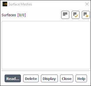
Surface meshes are used as background meshes for geometry-based adaption. Perform the following steps to read the surface mesh file into Ansys Fluent:
Open the Surface Meshes dialog box (Figure 6.24: The Surface Meshes Dialog Box). How you open this dialog box depends on the adaption method you plan to use:
If you are using the PUMA adaption method (the default for 3D), open the Auxiliary Geometry Definition dialog box (as described in Managing Auxiliary Geometry Definitions), select Surface Mesh from the Type drop-down list, and then click the button.
If you are using the hanging node adaption method, open the Geometry Based Adaption dialog box (as described in Performing Geometry-Based Adaption with the Hanging Node Method), enable the Reconstruct Geometry option, and then click the button.
In the Surface Meshes Dialog Box, click Read... and select the surface mesh file using The Select File Dialog Box.
Specify the units the mesh was created in (default is meters).
Note that you can also display and delete the surfaces using Figure 6.24: The Surface Meshes Dialog Box.
Continue performing the adaption:
If you are using the PUMA adaption method (the default for 3D), enable the Reconstruct Geometry option in the General Adaption Controls dialog box, set up the geometry-based adaption using the Manage Geometry-Based Adaption dialog box, and perform adaption as described in Refining and Coarsening.
If you are using the hanging node adaption method, make a selection from the Wall Zones list in the Geometry Based Adaption dialog box, click , set up the adaption in the Geometry Based Adaption Controls Dialog Box that opens (as described in Performing Geometry-Based Adaption with the Hanging Node Method), and perform adaption as described in Refining and Coarsening.