


Once cross sections are assigned and offset, they must be aligned to ensure they have the proper orientation.
To distinguish boundary edges, use the Edge Coloring option.
For line body edges, you will notice that each one has a small alignment triad shown with it, as shown in the picture below. The blue arrow identifies the edge's tangent direction, while the green arrow represents the alignment vector. It is this green arrow that defines the +Y direction of the cross section on the edge. The green arrow is defined by a reference direction, which is set through an Apply/Cancel button property for line body edges. A line body edge's alignment becomes invalid when its reference direction is parallel to the edge's tangent direction.
By default, initially all line body edges are aligned in either the global +Z direction, or if that would be invalid, the global +Y direction. The text for this property will indicate if +Z or +Y is being used and will be colored if a valid alignment edge has not been selected. While a default alignment results in valid edge orientation for most line body edges, it does not necessarily mean the cross section is aligned in the desired manner. You should check the alignment arrows of your edges or inspect the line bodies with their solid facet representation to ensure that your cross sections have the desired alignment on the edges. See DesignModeler Viewing for more information on line body display modes.
Note: The line body's state icon can either be red or yellow if the alignment is invalid. For more information see Body Status.
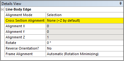
To set the line body edge's alignment, first select the edge in the Graphics Window. A property called Cross Section Alignment will appear in the Details View.
However, when edges are shared with Surface Bodies, the Line-Body Edge details may not appear.
Click the desired Line in the Graphics Window, then look at the "Selection Rectangles" in the lower left of the Graphics Window. Click through these as usually the last one is the Line Body. Click the rectangle will allow you to align/realign cross section in the Details.
If there is no alignment direction defined for the edge, then the property will appear in yellow as "Not Selected". Activating the Apply/Cancel buttons of this property will place you in an alignment selection mode, where you may select entities in the Tree Outline or from the graphics on screen to define a reference direction. The reference direction may be any of the types described in Direction Reference, though usually plane normal directions are most often used. When you have selected the desired direction reference, you can assign it by clicking the Apply button. To preserve the previously assigned reference direction, click Cancel. To clear the reference direction from a line body edge, you can clear the selection, then click the Apply button. The direction reference will be cleared and the default global +Z or +Y direction will again be used.
In addition, type, pointing towards a point, is added in to the types described in Direction Reference which will be used only when one point is selected. In this case, the alignment direction of all the selected entities will direct towards the point.
You can also change the Alignment mode to Vector, and enter an X, Y, and Z direction for the alignment vector. When not in 'Vector' mode, these fields are used to show the direction of the current alignment selection (or default), though they will be read-only.
In addition to the default or specified alignment, you can also specify a 'Rotate' angle. This rotation will be applied after the alignment is processed.
There is also an option to align the cross section with respect to the opposite end of the edge, called 'Reverse Orientation'. If you set this to Yes, it will move the alignment triad to the opposite side of the edge and reverse the edge’s direction. This also affects the direction of any additional 'Rotate' angle. Because this is an operation that modifies the edge, it is not permitted on Workbench bodies. To reverse the orientation of an edge belonging to a Workbench type body, apply the Conversion feature to make the body a DesignModeler type body first.
Finally, when finished editing Cross Section Alignment properties, ESC, Generate, or reselection the Select icon can be used to easily clear the Details View display.
Note: If a body undergoes a transformation after aligning its edges, the alignments do not move with it. The original alignment based on the selected direction will still apply.
Frame Alignment
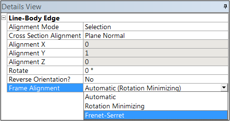
It is important for Line Edges in DesignModeler to be oriented correctly for the meshing processing that will occur downstream. During meshing, a moving frame is applied to a Line Edge as it is meshed to determine the orientation of individual elements. The moving frame can be calculated in one of two ways: either by using a rotation minimizing algorithm, or by using the Frenet-Serret algorithm. By default, DesignModeler will attempt to determine the proper frame on its own. Most of the time it assigns the frame correctly, but it may not always be able to make the optimal assignment. For such cases, you can use the Frame Alignment property shown in the image below to choose the desired frame alignment algorithm:
Automatic – DesignModeler suggests the frame alignment on its own. This is the default.
Rotation Minimizing – This alignment algorithm seeks to minimize twisting of the profile as it is swept along the edge and is suitable for most curves.
Frenet-Serret – This alignment algorithm is better suited for helical curves which have constant curvature and torsion.
Select Unaligned and Invalid Line Edges
When you choose one or more Line Bodies from the Tree Outline, and nothing else at the same time, along with the Hide and Suppress options, the right mouse button may present one or two additional options, Select Unaligned Line Edges and Select Invalid Line Edges. These options look through the Line Bodies you have selected and place any unaligned or invalid edges it finds into the selection set. Then it takes you to the option to change the alignment, just as though you had manually selected these Line Edges.
Note: The line body's state icon will be red if the alignment is invalid. For more information see Body Status.
The table below illustrates the cross section alignment of an edge that is valid.
| Step One: Select the line body edge you wish to align the cross section on. |  |
| Step Two: Activate the Apply/Cancel buttons for the Cross Section Alignment property. |  |
| Step Three: Select the desired direction reference by clicking in the Tree Outline or Graphics Window. |  |
| Step Four: Click the Apply button to lock in your choice. |  |
To make cross section alignment faster, you can also assign direction references to multiple edges at once. By using the Ctrl key or by using box selection, you can select multiple line body edges. In the Details View, you will see the number of line body edges selected at the top of the property group. Though the properties shown are specific to the first line body edge selected, the cross section alignment will apply to all selected edges. Below is an example of what you would see when four line body edges are selected.
Other Cross Section topics: