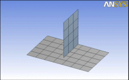
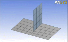
Shared Topology occurs when bodies are grouped into multibody parts. It allows for a continuous mesh across common regions where bodies touch, instead of having to define Contact Regions in the Mechanical application. Consider the example below. The models shown in both pictures are identical. The bodies on the left are two separate bodies, meshed independently. The connection between them must be defined by a contact region in the Mechanical application. The bodies on the right have been grouped into a part in the Ansys DesignModeler application. These bodies share topology in the region where they are in contact, so the mesh is continuous across the part. It is often, but not always, more desirable for the analysis to have a continuous mesh across the parts than to use contact.
 |  |
It is important to understand how shared topology works in the Ansys DesignModeler application so you can have better success with multibody parts. There are several key elements to shared topology.
First, the bodies you see in the Ansys DesignModeler application do not immediately share topology. Each body in the part is treated as its own separate entity with respect to modeling operations. Common regions among the bodies in the part are not combined until the model is transferred out of the Ansys DesignModeler application or a Share Topology feature is added to a model with the Share Topology toggle button on the 3D Features Toolbar. Therefore, to see the shared topology, either you must transfer the model to the Mechanical application or turn on the Share Topology toggle in the Ansys DesignModeler application.
Second, the method in which shared topology is created varies depending on the types of bodies that make up your part and the type of analysis you wish to perform.
The following sections provide more information about shared topology:


