


What kind of problem are you having?
Other Simulation Processing Issues:
I am processing my simulation but no output files are being created
Particles stopped flowing before my simulation was done processing
I want to use a Pascal-based GPU card instead of the recommended CUDA-based one
I cannot find where to set the number of cores for CPU processing
A fiber or other particle shape disappeared from my simulation during processing
I cannot resume processing my older simulation in the latest version of Rocky
My inlet stopped injecting particles for a long time and then later resumed it
See Also:
What kind of problem are you having?
I get a "runtime" or "system resource" error when I try processing my simulation
I get a "CPU" or "GPU" error message when I start processing my simulation
I get a "Simulation setup failed" message when I start processing my simulation
I got a message saying concave particles are not allowed in my Rocky version
I get a "Failed to write the log" message while processing my simulation
I get an "Error copying memory from device to host" message when I try processing my simulation
I get a scripting error when I attempt to run the simulation in batch mode
I get a "Server returned a fault exception" error when running a script in batch mode
See Also:
If you get a "runtime" or "system resource" error when you try processing your simulation, then your system probably cannot handle the amount of data you are trying to process.
See My simulation is taking too long to process for suggestions.
Most users of Rocky will have single-instance licenses, which means that only one instance of the Rocky solver can be running at any one time. For these users, it is possible to use the Rocky Scheduler program to run multiple simulations in series, or one-by-one, but not in parallel or simultaneously.
If you have a single-instance license and attempt to start processing more than one simulation at a time, you will get a "No Solver license available" message for all but the first simulation, as it will be using the single license that was available. Once that first simulation is done processing, the license will be freed up to be used by the next simulation in the queue, and so on.
If you have a need to process multiple simulations simultaneously, please Submit a Support Request or contact your Rocky representative to ask about upgrading to an unnumbered Rocky license.
See Also:
If while processing your simulation, you see a "Failed to write the log" message on your Rocky screen or in the Rocky Scheduler Progress column, this likely means that Rocky has stopped processing your simulation for one of the reasons explained below.
Important Because of the reasons below, when choosing to processes very long or complex cases-especially when over a network -it is important to periodically check the status of your simulation to ensure that loss of connectivity or other issues haven't stopped it from processing.
This version of Rocky requires continuous access to the .rocky20.log file in order to process your simulation. This requirement means that when processing over a network, any loss of connectivity between the system running Rocky and the network location storing your Rocky files will result in an automatic stop of simulation processing.
This is done to avoid the situation where Rocky continues to process your simulation but is unable to save your data. Preventing the simulation from processing further helps avoid any losses or breaks in your simulation data collection. This allows you to simply resume processing your simulation once connectivity is reestablished, rather than having to start processing over from the beginning.
To resolve this, check your network connection, and then resume processing your simulation again.
If the drive to which you are saving your Rocky files becomes too full to add more files, you might also see this error.
To resolve this, do one of the following:
Clear your current drive of other files (unrelated to your current simulation) to make more space, and then resume processing your simulation again.
Close Rocky, and then transfer all files related to your current simulation to a different drive with more space, reopen the in-process simulation, and then resume processing to this new location.
See Also:
When you click the Start or Resume button to process your project, you might encounter one of the following error messages.
Fail to checkout additional CPU licenses required
Teaching licenses can't use more than 4 cores
Designer licenses can't use more than 8 cores
These CPU-related messages can happen when the simulation was configured to run on more CPUs than were available or allowed on the license when the simulation was started. To solve this issue, lower the Number of Processors value on the Solver | General Settings tab.
Teaching licenses can't use GPU
Designer licenses can't use GPU
No GPU enabled License available
These GPU-related messages can happen when the simulation was configured to run on more GPUs than were available or allowed on the license when the simulation was started. To solve this issue, either lower the Target GPUs value on the Solver | General Settings tab, or change the Simulation Target to CPU.
If lowering your CPU or GPU values does not solve your problem, please Submit a Support Request for further assistance.
See Also:
When importing custom particles, Rocky enables you to import both convex and concave shape designs. (See also Import Custom Particle Shapes.) However, if you want to process a simulation with concave-shaped particles, you will need a special Rocky license. If you do not already have this license when you start processing your simulation, then you may see one or both of the following messages:
Simulator critical message: Concave particles are not allowed for this version
(From the Status panel) This version of Rocky cannot use concave particles.
To resolve this issue, do one of the following:
Submit a Support Request or contact your Rocky representative to learn about upgrading your license to include support for processing concave particle shapes.
When importing custom shapes, ensure you choose only convex shapes.
See Also:
There may be several reasons why you might get a "Error simulating" or "Simulation error" message after you resume or start processing your simulation as explained below.
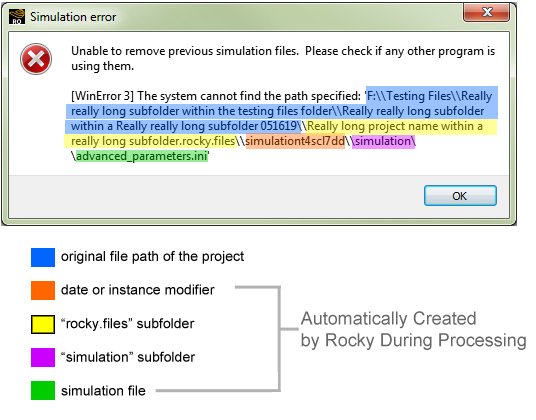
One reason you might get these messages is because the file path of the simulation file Rocky is attempting to access is too long.
The maximum number of characters that Windows allows on a full file path is 260. But due to the way Rocky creates one or more subfolders for your project to store files created during processing, it is possible for you to create a project with a shorter file path that then results in simulation files with paths that are too long for Rocky to access.
For regular Rocky projects, this includes a "rocky.files" folder that duplicates the name of your project, a "simulation" subfolder, and various output and log files (Figure 1), all of which add greatly to the character count of your original project path.
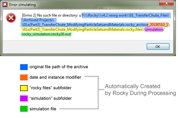
This is also true for projects restored from a Rocky Archive (Figure 2).
Figure 8.16: Example error when Rocky attempts to access a restored archive project file with a long path
Rocky adding these additional subfolders and files after processing is why you may not be notified that your file path is too long until Rocky attempts to access the processing files within these subfolders. That can happen during processing or when you try to resume a stopped simulation.
To resolve this issue, ensure that your initial project file path is short enough to account for the length of the subfolders and simulation files that will be created after processing.
Another reason you may get these messages is because another program (such as Windows Explorer) is accessing the simulation directory when you try to re-start processing a simulation from the beginning. (See also Start Processing a Simulation from the Beginning.) This happens because Rocky erases the previous simulation directory before starting, and on Windows you cannot delete a directory if another program is using it.
To resolve this issue, ensure that other Windows programs are not accessing the simulation directory before you start processing your simulation from the beginning again.
See Also:
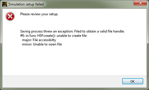
There are several reasons why you might get a "Simulation setup failed" message after you click the Start Simulation button to process your project, as explained below.
The maximum number of characters that Windows allows on a full file path is 260. If Rocky cannot access the simulation files that lie inside the project's directory because the path it wants is over the limit that Windows allows, it will not be able to process your simulation and will display a "Simulation setup failed" error (Figure 1).
Because of this limitation, it is a good idea to stay well below the character limit when saving your project. (See also I get an "Error simulating" or "Simulation error" message when I resume or start processing my simulation.)
If you set particle size or input parameters in such a way that results in too many particles (millions more than Rocky can handle, for example), Rocky will not process the simulation and will display a "Simulation setup failed" error (Figure 2).
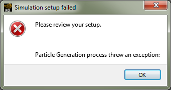
Because of this, it is best to set your particle size and particle input parameters in a way that results in no more than 20 million particles.
See Also:
When you are processing your simulation, the Simulation Log panel displays any solver-related warnings or information that can happen during processing (see also About the Simulation Log Panel.)
Some of the more asked-about warnings and errors are explained below. Note: This is not an exhaustive list.
If you get a warning that says "Estimated upper limit of surface velocity changed" (Figure 1), Rocky is letting you know that a sudden change of velocity happened during the simulation. These spikes are important for you to be aware of as they could indicate that something is wrong with the forces calculations. By alerting you to these occurrences, you can better decide whether further investigation is warranted.

This message is most common during the injection phase, as particles typically enter the domain with the minimum velocity possible for the combination of inlet area, inlet time, particle mass flow, and acceleration due to gravity. In this scenario, the increase in the velocity is expected and, therefore, these messages can likely be ignored.
However, in a scenario where you do not expect huge increases in the velocity (for example, a mill operating under steady state conditions), this message can alert you to potential issues that you can then investigate. You may determine after investigation that the velocity increase is a correct simulation result or you may find that it indicates numerical issues (for example, large overlaps or incorrect forces calculations) that may require changes to your simulation setup.
Rocky decides whether or not to show this warning-and what it displays if it does-in the following manner:
At the beginning of the output period, Rocky has a value of the relative velocity from the previous output period. In the example case shown in Figure 1, it was 0.6 m/s.
During the current computing output period, Rocky monitors the relative velocities. If it happens to be higher than 50% of the value it had from the previous output, it triggers the warning that velocities have increased more than 50%. In the example case above, it has computed a relative velocity of 5 m/s, which is 833% higher than the value it started with. The first line of the warning contains this info.
If this warning was triggered, Rocky will give you the statistics of the output, at the end of this output. It will give you the minimum and maximum relative velocities for particles and boundaries for the entire output. In the example case above, the maximum relative velocity was 10 m/s and the minimum was 0.3 m/s. The maximum velocity is higher than the one printed in the first line because that one was the velocity that launched the warning, while the maximum velocity happened later in this output period.
At the next output period, Rocky will check if the velocity is 50% higher than 5 m/s. If so, a new warning will be written to the Simulation Log.
If you get a message about "Contacts overlap" (Figure 2), Rocky is letting you know that the number of particle-to-particle or particle-to-boundary contacts had an overlap higher than one or more of the levels defined in the Contacts Overlap Monitor module. The overlap percentage is determined by the size of the smallest particle in the contact pair. (See also About Monitoring Overlaps.)
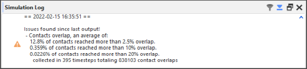
Monitoring your contact overlaps is important as Rocky is based on the soft-sphere approach, which uses the overlap value in order to compute collision forces. Large overlap values can lead to serious stability and accuracy issues in a simulation.
For example, when default Overlap Levels are used in the Contacts Overlap Monitor module, Rocky warns you when any overlaps higher than 2.5%, 10%, or 20% happened in the simulation, and also gives you the number of contacts that had large overlaps within that output. Typically, overlaps of 2.5% might be considered acceptable but simulations with overlaps larger than 10-20% should typically not be trusted.
Rocky decides whether or not to show a message or warning-and what it displays if it does-in the following manner:
If no overlap reaches more than Overlap Warning Level #1 (2.5% by default), no message is given.
If any overlap reaches more than Overlap Warning Level #1 (2.5%) but less than the other two, an info message is given.
If any overlap reaches more than Overlap Warning Level #2 (10% by default) but less than the other level, a warning message is given.
If any overlap reaches higher than Overlap Warning Level #3 (20% by default), a warning message is given.
See Also:
When you click either the Start or Resume button to process your project, you might encounter a Simulator critical message reporting an "Error copying memory from device to host" (Figure 1).
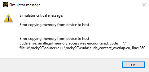
There are several reasons why you might get this error, including:
There isn't enough GPU memory to either start or resume the simulation. In this case, the solution is either to adjust your case setup to require less memory, or to select a higher-memory GPU or multi-GPU resource, and then try processing again.
The driver for the single GPU or multi-GPU resources is outdated. In this case, the solution is to update your GPU drivers, and then try processing your simulation again.
See Also:
When you click the Start button to process your project, you might encounter a Simulation setup failed error reporting that "Particles composed of Multiple Elements can't have size defined." (Figure 1).
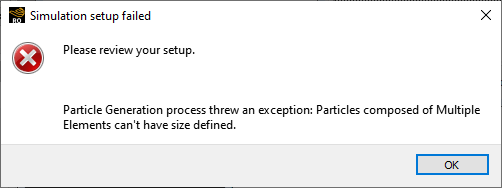
This situation happens when you have defined a Particle set with Multiple Elements (also known as meshed particles) that was then used for a Custom Input whose definition CSV file includes a Size column. Because Rocky allows only a single size for multi-element particles, it will not support this Size setting for Custom Inputs.
To resolve this error, do either of the following:
Remove the Size column from your Custom Input's definition file. Doing so means that only the single size you have defined for the multi-element Particle set itself will be used for all particles released by that Custom Input.
Change the Particle definition for your Custom Input to instead be a Particle set made of single-element (rigid) particles.
See Also:
If you have a Rocky simulation that you are attempting to run (either in Rocky or through Ansys Workbench) without the Rocky UI open (also known as "batch mode"), and you have scripts for tasks that require the Rocky UI to be open, you might get an error that says something similar to the following:
NotImplementedError: Error when executing scripting command: ExportAnimation. Arguments: {`context_id': `
                project.vizu_window_subjects_container.vizu_window_subject_00001.animation_context', `filename': `\\test.avi', `mode': `video'}n"}
This might happen if you try to run scripts in batch mode for the following tasks:
Creating and exporting an animation.
Creating and exporting plots.
Creating and exporting images of 3D View windows.
To resolve this issue, ensure that any scripts you are using in batch mode do not require the use of the Rocky UI.
See Also:
If you have a Rocky simulation that you are attempting to run (either in Rocky or through Ansys Workbench) without the Rocky UI open (also known as "batch mode"), and you have scripts for tasks that make use of matplotlib using Qt as a backend, you might get an error that says something similar to the following:
CookComputing.XmlRpc.XmlRpcFacultException: Server returned a fault exception:
                [1] <class `TypeError'>:_init_() missing 1 required positional argument: `figure'
This can happen if the script tries to export an image when the Rocky UI is closed, which also means there is no Qt window nor context available.
To work in batch mode, you must change the script so that matplotlib uses a non-interactive backend, such as `svg'. An example of this code change is provided below:
:Command:import matplotlib
matplotlib.use(`svg')
import matplotlib.pyplot as plt`
See Also:
If your simulation is taking longer than you expected to process, try doing one or more of the following:
Run only one simulation at a time on any one machine.
Increase your processing power and/or try running the simulation on a GPU. (See also About Starting a Simulation.)
Limit the particle complexity, including reducing the number of shape sides, corners, and size distributions used. (See also About Adding and Editing Particle Sets.)
Reduce the particle mass flow rate. (See also About Adding and Editing Particle Inputs.)
Make your boundary triangle sizes larger.
Increase your Timestep Duration. (See also About the Simulation Summary.) This can be done by increasing the size of the particles (see also Set Particle Size Ranges), reducing the Young's Modulus (see also About Modifying Material Compositions), and/or reducing the Loading N-Steps (see also About Solver Parameters. Note: Loading N-Steps should not be set lower than 10.
See Also:
Before you are able to process a simulation, you need to set up each of the following items:
One Particle set. (See also About Adding and Editing Particle Sets.)
One Input. (See also About Adding and Editing Particle Inputs.) Note: If the input is a Continuous Injection type, then one inlet is also required. The inlet can either be from a default feed conveyor or from a separate inlet geometry that you have added into the simulation.
Tip: Use the information on the Status panel to help you solve issues quickly. (See also Double-Click the Status Panel to Jump to the Appropriate UI Location.)
See Also:
There are several reasons why you might be getting unusual results when you process your simulation. See below for possibilities.
You might have imported hidden boundaries. When you create your boundary components in a CAD program like Ansys SpaceClaim, you have the ability to hide components or layers of components. All boundaries-hidden or shown-will be imported into Rocky with an STL, XGL, or DXF 3D faces file, so it is best to remove the boundaries you do not want from the CAD program before importing the file into Rocky. This is primarily an issue when boundary walls overlap and create a case for trapped particles (see below).
You might have overlapping inlets. An inlet will delay dropping particles until it detects that there are no other particles in its way. If you have set an inlet in the particle path of another inlet, this can cause the downstream inlet to produce strange spurts of particles as it starts and stops its particle flow to account for other particles in its way - You might have trapped particles. With moving boundaries, particles can become trapped inside a boundary wall when the new position for the boundary slices through the middle of a particle before the particle has a chance to recalculate its new position. This can cause the trapped particle to shoot out in strange directions, like popcorn. To prevent trapped particles, try the following:
Move boundaries slowly to give the particles enough time to re-calculate their positions.
Avoid overlapping boundary walls.
As a last resort, select the Release Particles without Overlap Check checkbox on the Solver | General tab. (See also About Solver Parameters.)
Your simulation domain might be too small for your particle shapes. This happens most frequently with fiber shaped particles. (See also A fiber or other particle shape disappeared from my simulation during processing.)
If after taking the steps above you still get unusual results, please contact support for assistance. (See also Getting Help and Support.)
See Also:
If you have clicked Start on the Solver tab but see that no output files are being created, then one of the following events might be happening:
You have not yet updated the results using the Refresh button or the Auto Refresh checkbox on the progress toolbar. (See also Start Processing a Simulation from the Beginning.)
Your simulation is taking longer to process due to its complexity and/or a limited amount of processing power. (See also My simulation is taking too long to process.)
The Simulation Output Frequency might not be set low enough for the Simulation Duration you specified. In order for output files to be created, the Simulation Output Frequency value must be smaller than the Simulation Duration value. (For example, a Simulation Output Frequency of 5 for a Simulation Duration of 20 will yield 4 output files.) To lower the Simulation Output Frequency, do the following:
From the Data panel, select Solver.
From the Data Editors panel, select the Solver | Time tab.
In the Simulation Output Frequency box, enter a smaller number. (0.05 is the recommended default.)
Try processing your simulation again. (See also Start Processing a Simulation from the Beginning.)
See Also:
The speed by which the particles flow out of an inlet with continuous injection input is based upon the following criteria:
The particle mass flow rate of the input.
The size of the inlet.
The injection period of the input.
In general, the smaller your inlet and the shorter your injection period, the faster the particles will flow out of it. To have your particles flow slower, make your inlet larger, increase your injection period, and/or reduce your particle mass flow rate.
See Also:
About Inlet Parameters
In Rocky, there are several events that may cause your particles to appear as if they are going through the walls of a geometry during a simulation, examples of which are shown in Figures 1 and 2.
The most common reasons and possible solutions are discussed below.
In this version of Rocky, it is possible for you to set the limits of your Periodic Cartesian Domain to be smaller than your geometry limits and/or the coordinate limits of your domain. In doing this, however, you run the risk of having particles go through the walls of your geometries during the simulation.
This is likely to happen if a geometry has triangles with all three vertices lying exactly on the plane that defines the periodic limits in a direction; those triangles will not contact the particles even if the boundary motion leads the triangles away from the periodic limits. This can cause the particles to go right through the geometry.
To solve this, change the limits of your periodic domain to avoid having them line up exactly with the triangles of your geometry walls. (See also About Domain Settings Parameters.)
If the velocity of a particle is too high given both the time step and the stiffness of the item it contacts, it is possible for a particle to shoot right through the geometry. This can happen for any case where the relative velocity of two particles colliding or a particle and and a boundary colliding are high. For example:
When the initial particle injection speed is too high.
When the particle injection speed is low but you have a boundary accelerating or perhaps rotating the domain very fast, which during contacts can fling the particles through boundary walls.
Particle injection speed is based upon the particle mass flow rate, and the size of the inlet, and injection period of the input. So in general, to reduce your injection speed, make your inlet larger, increase your input injection time, and/or reduce your particle mass flow rate. (See also My particles are flowing too quickly.)
To slow down fast-moving geometries, you can adjust your velocity parameters using Motion Frames. (See also About Creating and Applying Motion Frames.)
When used with shaped particles, rolling resistance can cause strange behavior, including having particles go through boundaries and other unwanted behavior. It is therefore best to set Rolling Resistance to zero in these cases:
When you are using elongated particles (i.e., shapes with high aspect ratios).
When you have set your Tangential Force model to be Mindlin-Deresiewicz. (This is due to a known issue that could lead to an unstable Angle of Repose. See also Physics and Force Limitations.)
(See also About Adding and Editing Particle Sets.)
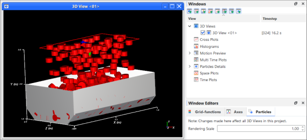
A visual overlap between the particles and the geometry can occur, for example, when the geometries are imported as a surface. Because a surface boundary has no thickness, the particles can sometimes appear to come through (or "bleed" through) it (Figure 2). This affects only the visualization of the case and has no effect upon the results nor analyses.
To resolve this issue, try lowering your Particle Rendering Scale. (See also About Using the Window Editors Panel to Change All 3D Views in the Project.)
See Also:
If your simulation appears to be processing and is generating *output files* but you are seeing no particles appearing on your screen, one of the following events might be happening:
You haven't yet created a 3D View window, which is the method by which you visualize geometries and particles. (See also View Geometries, Particles, Points, and Fluids in 3D.)
You have disabled the Particles entity on the Data panel. (See also Show/Hide Components by Using Eye icons and Checkboxes.)
The particles have been set as a Solid color the same color as the 3D View background, rendering them invisible. (See also About Using the Coloring Tab to Change a 3D View.)
No particles have entered the domain yet. This might happen if the continuous injection input has not yet become active, perhaps due to the start and/or stop time settings, or because the mass flow rate is set low enough that there is a long break between individual particles being released (see also About Adding and Editing Particle Inputs). In this case, it is possible that you happen to be viewing a timestep where particles have not been released yet, and waiting for further timesteps to be calculated might resolve the issue.
You have not yet updated the results using the Refresh button or the Auto Refresh checkbox on the progress toolbar. (See also Start Processing a Simulation from the Beginning.)
See Also:
If at any point during the simulation, a particle cannot completely enter the simulation area, no more particles will enter the simulation and the particle flow will stop. A particle can be prevented from entering the simulation area by a boundary or another particle.
For example, if a chute gets blocked and particles back up close enough to the entry point (an inlet or the top of a feeder box, for example), the particle flow will stop. Or, for example, if the top of a feeder box is sloped enough to not allow enough space for a particle to fully enter at the corners, the particle flow will stop.
To fix this issue, try one or more of the following solutions:
Add a vertical lip to the top of your feeder box.
Make the inlet smaller or higher.
As a last resort, select the Release Particles without Overlap Check checkbox on the Solver | General Settings tab. (See also About Solver Parameters.) Note: Turning off the overlap check can lead to unusual results as overlapped particles might add extra energy to the particle flow, which can affect other particles and boundaries.
See Also:
Rocky comes with a separate program called Rocky Scheduler that is used to process multiple simulation projects at once. The Rocky Scheduler program is saved to the same directory as the main Rocky program. (See also Open the Rocky Scheduler Program.)
Batch mode may also refer to running Rocky through the command line. (See also Appendix G: Perform Tasks from the Command Line or Journal.)
See Also:
Pascal-based GPUs are still CUDA-based, so they will work just fine for processing in Rocky. The Pascal title refers to the architecture of the GPU, as Maxwell did to the previous generation. Maxwell was 28 nm and Pascal is 16 nm chip size.
See Also:
You set the number of cores you want to use during processing in the Number of Processors box, which is located on the Solver | General tab. (From the Data panel, click Solver and then from the Data Editors panel, select the Solver tab and then the General sub-tab.)
See Also:
If you see a notification from Rocky that your GPU card is not CUDA compatible, and you know your card is supported by Rocky (see System Requirements for a list of supported GPU cards), then you have most likely installed a new version of Rocky that requires a newer driver for your GPU card. Even if you have automatic updates set and your device manager shows your card as up-to-date, you may still benefit from a manual driver update. (See Best Practices for Installing a New Version of Rocky for specific instructions.)
See Also:
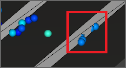
If during your simulation, you notice that a fiber or other particle shape disappears suddenly from your screen, it is most likely caused by the particle reaching the limits of the domain.
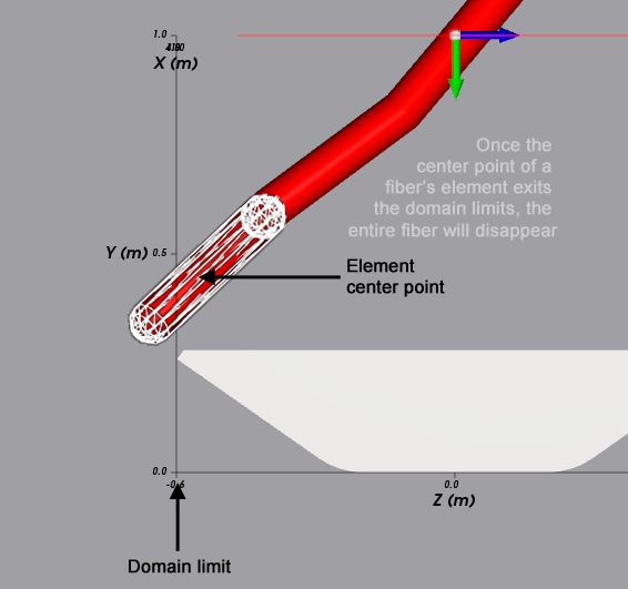
In Rocky, all particle shapes exit the domain as soon as the center of the shape reaches the domain limits. Because fibers are made up of many separate smaller shapes called elements, it is the center of the element and not the fiber shape itself that is counted in these cases. This means that even if only a small portion of the fiber reaches the domain limits, the whole fiber will disappear (Figure 1).
Figure 8.25: A fiber particle just before the center of one of its elements reaches the domain limit and disappears from the simulation
Because of this key difference, disappearing fiber particles are much more noticeable, and could happen with more frequency than with other particle shapes.
It is therefore important that when simulating fiber shapes you pay extra attention to the size of your domain. Ensuring that your domain is large enough to support the extra length of a fiber particle will help ensure that your particles do not disappear.
See Also:
You may only resume processing your stopped simulation if the simulation was last processed in the same major version of Rocky as the version you are using now. For example, if you started processing your simulation in version 4.1.0, you may resume processing it in any 4.1.x version released thereafter, but may not resume it in any version of the next major release of 4.2.x, and so on.
For these latter situations, you must start processing the project again from the beginning. (See also Start Processing a Simulation from the Beginning.)
See Also:
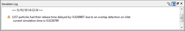
While processing a simulation, Rocky's continuous injection algorithm for inputs tries to release particles into the simulation without causing any particles to overlap other particles. If Rocky predicts that an overlap will happen, it will hold off injecting the next layer of particles for a period of time, then it will try again. If an overlap is still predicated at that later point, it will hold of releasing the layer again for another period of time, and so on.
When this kind of injection delay happens, Rocky will provide you with a warning in the Simulation Log panel (Figure 1) as "N particles had their release time delayed by X due to an overlap detection on inlet".
If you find Rocky is waiting too long to release particles, you can try adjusting the following parameters:
The injection waiting period. In Rocky, this is called Overlap Particles Delay and can be found on the Solver | General tab. The default value is 0.025 s. (See also About Solver Parameters.)
The size and location of your inlet. This can help provide more space and simulation time for particles to be injected.
The mass flow rate and injection timeframe of your continuous injection input. This can help reduce the amount of particles that are released. (About Adding and Editing Particle Inputs.)
The shape, size, and/or orientation of your particle set. (See also About Adding and Editing Particle Sets.)
See Also:
While the Volumetric Inlet method for Particle Input has several options that provides maximum flexibility with regards to your simulation set up, this complexity can also increase your chances for mistakes.
Use this topic to learn about the most common issues and how to avoid them.
For Volumetric Inlet, Rocky provides a particle estimate on the Info tab assuming that there are no boundary limits to consider, and assuming a Gap Scale Factor equal to 1. This means that you can set a Mass much higher than the box and gap you define will hold, but Rocky will not know that until after the simulation is processed.
To avoid this, ensure that you are entering a Mass value appropriate for the Particle set, gap factor, and box volume.
If the Seed Coordinate of your Volumetric Inlet happens to land directly on the bounds of a geometry component, Rocky may have trouble calculating the fill due to overlaps with the boundary.
To avoid this, ensure that you locate your Seed Coordinate well away from the boundaries of your simulation geometries.
If your Volumetric Inlet properties result in fewer than 3 particles, the Volumetric Inlet will not work, you will get no particles injected into your simulation, and you might get an error when you try to process your simulation (Figure 1).
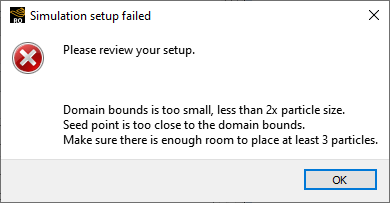
Volumetric Inlet Inputs require at least 3 particles in order to create the "Seed".
To fix this, increase your Mass, reduce your Particle Size, reduce your Gap Scale Factor, and/or make your fill area larger to accommodate more particles.
Tip: To see an estimate of how many particles Rocky expects to generate given the parameters defined, view the information on the Info tab for the Volumetric Inlet Input you are defining. Note: Keep in mind that the estimate assumes there are no boundary limits to consider and assumes a Gap Scale Factor equal to 1. This means that if you have set your particle Mass higher than the box and gap you define can contain, the particle estimate on the Info tab will show a higher number than what will actually be injected.
See Also:
Most setup parameters (see also see also Setting Up a Simulation) you are unable to change while your simulation is actively processing. This is because changing those parameters would have an effect upon the calculations that are already in process.
You will know that a parameter is not able to be changed during processing when it appears disabled (i.e, grayed out) in the UI.
The one exception to this rule is for the setup options on the top most Study entity (see also About Study Parameters), which can be changed at any point, even during active processing. This is because while these settings do affect the project file, they do not affect the underlying calculations being performed.
To change any of the other setup parameters, you must first stop your simulation (see also Stop a Simulation from Processing). At that point, the only other parameters besides the Study entity ones that you can modify without invalidating your results are the Execution options on the Solver | General tab, and the options on the Solver | Advanced tab (see also About Solver Parameters). If you change any of these parameters while your simulation is stopped, you will still be able to Resume processing (see also Resume Processing a Stopped Simulation) after making your changes.
Any other setup parameters that you want to modify will require you to either delete your results or make a copy of your project setup before you will be able to change them (see also Setting Up a Simulation). It is therefore important to ensure that your settings are correct before you begin processing.
While it is not possible to change most of your setup parameters during active processing, you should still be able to create and modify non-setup parameters such as those for data viewing and analysis (see also Analyzing a Simulation). This includes User Processes, Properties, Curves, and windows such as 3D Views and plots. These all make use of the data Rocky calculates during processing-and will therefore be limited to only the data that has been processed-but themselves have no affect upon how the calculations are made. Therefore, you are able to make use of these forms of analysis during active processing.
See Also:
If you have a particle that when simulated, drops from a certain height, bounces, and then later bounces higher-as if the energy is increasing over time-you have likely defined the following parameters in your simulation:
A non-round particle shape with Enable Rotations turned on (default).
The interaction between the material used for the particle and the material used for the boundary it is colliding with has a Restitution Coefficient between 0.5 and 1.
The timestep is calculated automatically (default).
In this particular situation, the particle height might seem to increase after each collision. This is because the timestep that Rocky automatically uses by default is not small enough to accurately simulate rotating non-round particles that have no (or almost no) dissipation. (No dissipation is represented by a Restitution Coefficient equal to 1.)
In Discrete Element Modeling (DEM), the dissipation is rarely zero and, therefore, the restitution should rarely be equal to 1. Rather, typical restitution should be less than 0.5 and the default timestep works fine for these cases.
For restitutions above 0.5, the default timestep is no longer sufficient and if left as default, will cause errors to accumulate in the simulation. The closer to 1 is your restitution value, the more errors are expected to accumulate, which can result in the inaccurate particle behavior described above.
The best way to prevent errors from accumulating in these situations is to decrease the timestep. The closer the restitution value is to 1, the more significant the timestep decrease should be.
Another thing to take note of in this situation is the size of the triangular mesh of the colliding boundary in relation to the particle size. If the triangular mesh is significantly smaller than the particle, it creates multiple contacts for the impacting particle, decreasing the accuracy of the simulation. If you increase the size of your triangles so that the particle impacts just one triangle at a time, for example, you will get more accurate results.
In summary, to resolve this issue, try one or more of the following:
Use Spheres or other rounded particle shapes. (See also About Adding and Editing Particle Sets.)
Turn off Enable Rotations. (See also About Adding and Editing Particle Sets.)
Set the Restitution Coefficient values to between 0.1 and 0.5. (See also About Modifying Materials Interactions and Adhesion Values.)
Decrease the timestep. (See also About Solver Parameters.)
Increase the size of your colliding boundary's triangular mesh.
See Also: