


The engineers who developed and tested Rocky have compiled the following set of best practices to help you get the most out of using the software. These recommendations are best used in conjunction with the user assistance content in this manual.
What would you like to learn more about?
See Also:
New versions of the Rocky software are released on a regular basis, which give you access to various improvements, fixes, and additions to the software. There are some steps you can take to help ensure success with the process of installing or upgrading to a new version of Rocky, including the following:
Manually update the driver software for your GPU cards, even if the device manager shows that it is up-to-date. Oftentimes, the NVIDIA automatic update system does not properly install the latest drivers, and having older drivers may prevent Rocky from working properly. Visit the NVIDIA website. and manually update your GPU driver to the latest that supports the CUDA 11.6 toolkit or higher.
Review the Release Notes. This is displayed automatically whenever a new version of the Rocky software is available for download, and lists all the new features and functionality that have changed since the last version. Knowing what has changed can help you locate the feature in the product and learn more about it in Help (this document). You can also view the Release Notes at any time from within the product. (From the Rocky Help menu, click Release Notes.)
See Also:
The amount of time it takes for Rocky to process a simulation depends upon many factors, including but not limited to:
The processing speed of the computer Rocky is running upon
Whether you are using CPU processing, GPU processing, or Multi GPU processing capabilities
The number, size, and complexity of the particles being simulated
The size of the simulation timestep, which is defined by particle size, density, Young's Modulus, and restitution coefficients
The size of the geometries
The simulation time (in seconds)
Whether the simulation files are being saved over a network
While there are no hard-and-fast rules regarding processing speed in Rocky, there are some steps you can take to speed up your processing time, including:
Use GPU or Multi GPU processing, and/or increase your processing power.
Reduce your particle stiffness, which is based upon the Young's Modulus and particle size. The default Young's Modulus of
 Pa can be safely reduced to
  -
-  Pa for narrow size distributions (1:3 or less). This should result in
a 3-10x increase in timestep, which will speed up your simulations. (See also About Modifying Material
Compositions.)
Pa for narrow size distributions (1:3 or less). This should result in
a 3-10x increase in timestep, which will speed up your simulations. (See also About Modifying Material
Compositions.)Use the Numerical Softening Factor to increase the size of your timesteps. (See also About Physics Parameters.)
Select a simpler, easier-to-calculate model for the Normal Force and/or Tangential Force option. (See also About Physics Parameters.)
Instead of composing your particle shapes from Multiple Elements (also known as meshing), choose a Single Element Composition. (See also About Adding and Editing Particle Sets.)
Increase your minimum particle size.
Reduce the complexity (sides, corners, size distributions) of your particles.
Shorten the simulation length.
Increase the size of your geometry triangles. The default value of 0.1 is recommended for all boundaries where you want to see wear data.
Run and save Rocky files locally; avoid processing and saving Rocky simulations over a network.
Run only one simulation at a time on any one machine.
To gain an understanding of how much faster GPU processing could be as compared with CPU processing, review the following blog: More GPUs = faster processing with Rocky DEM.
See Also:
Use the following recommendations when using a CAD program to create geometries geometries for importing into Rocky:
Orient your design around the origin. For example, when designing conveyor chutes, place the center of the head pulley at (0,0,0), and build your other components around it.
Include the conveyors in your design but do not import them into Rocky. It is easier to use the conveyors included with Rocky and only import your chutes or other geometries. Use the conveyor dimensions in your CAD design to size and position the Rocky conveyors accordingly.
Make your design as realistic as possible. Use actual dimensions whenever possible.
Remove any "hidden" boundaries before saving the file you want to import. Some hidden geometries might be imported into Rocky.
Color geometry components differently to make it easier to distinguish components before and after import.
See Also:
Use the following recommendations when setting up geometries in Rocky:
Only import your non-conveyor geometries into Rocky (i.e., your chute or mill). Use the conveyor designs included within Rocky for your conveyor components.
Make the conveyor settings as realistic as possible. Any error or shortcut taken in setting up geometries will result in false data.
Ensure that the triangle size of your feed and receiving conveyors are small enough to avoid deformation of the geometries. Larger triangle sizes (1m for example) might change the overall shape of the conveyor, making your simulation less realistic. It is recommended that the default value of 0.1 be used.
Note: Triangle size will not affect the shape of imported boundaries; just the default conveyors included with Rocky.
Ensure that your inlet is large enough to allow your largest particle to pass through, but still slightly smaller than your geometry opening. This will help prevent particles from getting "stuck".
When setting up multiple inlets, ensure that your inlet locations and Start and Stop Times are configured in such a way as to avoid Particle sets from overlapping during the simulation. An inlet will delay releasing its particles until no other particles from other Particle sets are in the way.
Note: This step is unnecessary if Release Particles without Overlap Check is selected on the Solver | General tab. (From the Data panel, click Solver and then from the Data Editors panel, select General on the Solver tab.)
When locating an inlet or default conveyor, first sketch its size and location in a CAD program and then use the resulting coordinates to properly place it within Rocky.
Ensure that particle speed equals belt speed by the time the particles reach the pulley. Adjust the loading length of the belt to achieve the desired result.
When setting up custom feeder boxes, ensure that there is enough vertical space between the wall of the box and the entry point of the particles (i.e. top of the feeder box or inlet) for your largest particle. If a particle hits a boundary or other particle before fully entering the simulation, all particles will stop flowing.
Note: This step is unnecessary if Release Particles without Overlap Check is selected on the Solver | General tab. (From the Data panel, click Solver and then from the Data Editors panel, select General on the Solver tab.) To prevent this from happening, do one of the following (see also in ???)
Make your inlet smaller.
Add a vertical lip to the top of your feeder box.
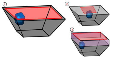
Figure 1: (1) Angled walls of feeder box prevents particle from fully entering simulation area; (2) Make the inlet smaller; (3) Add a lip to the top of the feeder box.
See Also:
Use the following recommendations when setting up particles in Rocky:
Calibrate your particle size, shape, and interaction settings to the real-world behavior of the material you are simulating. You may wish to use the Material Wizard and/or the Calibration Suite to help you with this task.
When setting particle friction values:
For rock or granular particles with rougher surfaces, set friction values to 0.6 - 0.7
For glass-like particles with smoother surfaces, set friction values no lower than 0.3
When testing out a new chute design, save time by running a quick simulation with Sphere particles to ensure your boundary settings are as you want them. This will take less time and will enable you to iterate on your design faster. Once your boundaries are set and verified, set up your shaped particle combinations and distributions and run that as a final step.
When using periodic Cartesian domains (previously known as "periodic boundaries"; see also About Domain Settings Parameters), ensure that your largest particle size is less than 0.4 times the distance between the Min Coordinate and Max Coordinate values for the periodic domain.
See Also: