


Rocky is a dynamic program with a code base that is continually being improved upon to better serve the needs of our customers. As such, there may be some features included in this version that are not fully developed or verified. These features are provided as a working example of future capabilities but there are limits to their practical usage as described in this section.
The below matrices communicate the program limitations of major features including breakage and GPU processing (Table 1), as well as feature compatibility with the various particle shape types and models (Tables 2 and 3).
To learn more about what feature limitations might be due to your license type, or for further information regarding the known limitations of other specific Rocky features and capabilities, see the additional topics listed below.
Table 1: Compatibility Matrix for Major Rocky Features
|
FEATURE |
Breakage |
GPU and Multi GPU Processing |
1-Way LBM |
Thermal Modeling |
1-Way Fluent |
2-Way Fluent |
Coarse Grain |
|---|---|---|---|---|---|---|---|
|
Breakage |
|
|
|
|
|
|
|
|
Energy Spectra Collection |
|
|
|
|
|
|
|
|
About Intra-Particle Collision Statistics |
|
|
|
|
|
|
|
|
Flip Count Property |
|
|
|
|
|
|
|
|
GPU and Multi GPU Processing |
|
|
|
|
|
|
|
|
Particle Tagging, including Divisions Tagging |
|
|
|
|
|
|
|
|
Particles Time Selection |
|
|
|
|
|
|
|
|
Residence Time Property |
|
|
|
|
|
|
|
|
1-Way LBM |
|
|
|
|
|
|
|
|
Saving an In-Process Simulation for Restart |
|
|
|
|
|
|
|
|
Extending the Duration of an In-Process or Completed Simulation |
|
|
|
|
|
|
|
|
Thermal Modeling |
|
|
|
|
|
|
|
|
1-Way Fluent |
|
|
|
|
|
|
|
|
2-Way Fluent |
|
|
|
|
|
|
|
|
Coarse Grain Modeling |
|
|
|
|
|
|
|


Table 2: Compatibility Matrix for Rigid Rocky Particle Shape Types Composed of Single Elements
RIGID PARTICLE SHAPES COMPOSED OF A SINGLE ELEMENT | Instantaneous Breakage | GPU and Multi GPU Processing | 1-Way LBM | Thermal Modeling | 1-Way Fluent | 2-Way Fluent | Coarse Grain Modeling |
|---|---|---|---|---|---|---|---|
Spherical Solid Sphere |
|
|
|
|
|
|
|
Rounded Corner Solid Sphero-Cylinder, Sphero-Polygon, Sphero-Polyhedron |
|
|
|
|
|
|
|
Sharp Cornered Solid Polyhedrons, Briquettes, Faceted Cylinders, and Custom Non-Concave-Shaped Polyhedron Particles |
|
|
|
|
|
|
|
Concave Solid Custom Concave-Shaped Polyhedrons |
|
|
|
|
|
|
|
Fiber Straight Fiber and Custom Fiber Particles |
|
|
|
|
|
|
|
Shell Custom Shell Particles |
|
|
|
|
|
|
|
Table 3: Compatibility Matrix for Flexible Particle Shape Types Composed of Multiple Elements (Meshed)
FLEXIBLE PARTICLE SHAPES COMPOSED OF MULTIPLE ELEMENTS | Discrete Breakage | GPU and Multi GPU Processing | 1-Way LBM | Thermal Modeling | 1-Way Fluent | 2-Way Fluent | Coarse Grain Modeling |
|---|---|---|---|---|---|---|---|
Convex Polyhedron Solid Polyhedrons, and Custom Non-Concave-Shaped Polyhedron Particles |
|
|
|
|
|
|
|
Concave Polyhedron Solid Custom Concave-Shaped Polyhedrons |
|
|
|
|
|
|
|
Fiber Straight Fiber and Custom Fiber Particles |
|
|
|
|
|
|
|
Shell Custom Shell Particles |
|
|
|
|
|
|
|
* Limitation still applies to projects processed in Rocky versions prior to v4. To remove the limitation, re-process the project in Rocky v4 or later.
[cross symbol] Features are compatible but do not interact.
** Note that the Radl et al. Coarse Grain Model is not currently compatible with Multi GPU processing.
See Also:
The below list defines the various limitations and restrictions for setting Physics components in Rocky.
Each simulation must have a Normal Force and Tangential Force defined; an Adhesive Force is not required.
Also, as specified in Table 1 below:
The Rolling Resistance Model of Type C: Linear Spring Rolling Limit does not work with the Tangential Force of Coulomb Limit.
The Tangential Force of Mindlin-Deresiewicz works only with the Normal Force of Hertzian Spring Dashpot.
When the Tangential Force of Mindlin-Deresiewicz is being used in a project with shaped particles, it is recommended that Rolling Resistance be set to zero (0) for any shaped Particle sets due to the fact that doing so could lead to an unstable Angle of Repose. (See also About Adding and Editing Particle Sets.)
The Adhesive Force of JKR works only with the Normal Force of Hertzian Spring Dashpot.
Both types of Rolling Resistance Models are incompatible with Concave Custom Polyhedron (Solid) particle shapes.
Table 1: Compatibility Matrix for Rocky Momentum Models
|
MODEL |
Rolling Resistance Model: Type A: Constant Moment |
Rolling Resistance Model: Type C: Linear Spring Rolling Limit |
Normal Force: Hysteretic Linear Spring |
Normal Force: Linear Spring Dashpot |
Normal Force: Hertzian Spring Dashpot |
Adhesive Force: Constant |
Adhesive Force: Linear |
Adhesive Force: JKR |
Tangential Force: Linear Spring Coulomb Limit |
Tangential Force: Coulomb Limit |
Tangential Force: Mindlin-Deresiewicz |
|---|---|---|---|---|---|---|---|---|---|---|---|
|
Rolling Resistance Model: Type A: Constant Moment |
|
|
|
|
|
|
|
|
|
|
|
|
Rolling Resistance Model: Type C: Linear Spring Rolling Limit |
|
|
|
|
|
|
|
|
|
|
|
|
Normal Force: Hysteretic Linear Spring |
|
|
|
|
|
|
|
|
|
|
|
|
Normal Force: Linear Spring Dashpot |
|
|
|
|
|
|
|
|
|
|
|
|
Normal Force: Hertzian Spring Dashpot |
|
|
|
|
|
|
|
|
|
|
|
|
Adhesive Force: Constant |
|
|
|
|
|
|
|
|
|
|
|
|
Adhesive Force: Linear |
|
|
|
|
|
|
|
|
|
|
|
|
Adhesive Force: JKR |
|
|
|
|
|
|
|
|
|
|
|
|
Tangential Force: Linear Spring Coulomb Limit |
|
|
|
|
|
|
|
|
|
|
|
|
Tangential Force: Coulomb Limit |
|
|
|
|
|
|
|
|
|
|
|
|
Tangential Force: Mindlin-Deresiewicz |
|
|
|
|
|
|
|
|
|
|
|
* For this combination of models, setting Rolling Resistance values are recommended only for spherical Particle sets. For shaped Particle sets, it is recommended that Rolling Resistance be set to zero (0).
The 2-Way Fluent Semi-Resolved method does not currently support Thermal Modeling. (See also About Using the 2-Way Fluent Semi-Resolved Method.)
Coarse Grain Modeling (CGM) is incompatible with all of the following features and functionality:
Particle breakage.
Particles composed of multiple elements (also known as Meshed). This includes flexible Fibers, Shells, and Solids.
The JKR Adhesive Force model.
The Velocity Dependent Restitution Model.
Non-drag fluid forces. This includes torque, virtual mass, and lift forces.
1-Way LBM CFD Coupling.
In addition, the Radl et al. Coarse Grain Model is incompatible with Multi GPU processing.
Important: When CGM is enabled, the results might differ significantly from those without CGM. This is due to an uncertainty that is incorporated within the numerical results, for the CGM is a mathematical manipulation to artificially increase the size of the particles. This kind of mathematical modeling needs to be used with care and evaluating if the results make physical sense.
See Also:
The below list defines the various limitations and restrictions for setting Geometry components in Rocky.
Geometries cannot have duplicate names. (I.e., two different geometry components cannot have the same name.)
Imported geometries with surface wear enabled have all of the following limitations:
They cannot have a Triangle Size that is too large relative to the geometry dimensions.
They cannot have a Motion Frame assigned with the Keep in Place option enabled (set as Global or Local). (Surface wear is incompatible with any motions without displacement.)
Imported geometries with Motion Frames assigned have all of the following limitations:
A Motion Frame with a Free Body Translation or Free Body Rotation motion(s) must be assigned to an imported geometry; having a Motion Frame with a Free Body motion but no geometry assigned to it is not supported.
For any given Motion Frame, the time intervals for two or more of the same kind of Free Body motions (Translation or Rotation) that share common directions (X and XY, for example) cannot overlap. This means that a Free Body Translation motion in the X direction cannot occur at the same time as a second Free Body Translation motion in the XY direction, but can occur at the same time as Free Body Rotation motion, or at the same time as a Free Body Translation motion on a different axis (Y, for example).
Note: Note: The time intervals are open at the end. For example, the intervals (0s, 10s) and (9s, 20s) overlap but the intervals (0s, 10s) and (10s, 20s) do not overlap because the second motion starts at exactly the stop time of the first.
Imported geometries with Geometry Replication enabled must have a Motion Frame assigned with at least one of the following motions: Translation, Rotation, Periodic Translation (Vibration), or Periodic Rotation (Pendulum). (This means that geometry replication features are not compatible with free body motions.)
See Also:
The below list defines the various limitations and restrictions for setting Particles and Inlets in Rocky.
GENERAL LIMITATIONS FOR PARTICLES AND PARTICLE INLETS
There must be at least one particle set and Inlet defined in the simulation.
A simulation may have both the Thermal Model enabled and have collections for Intra-particle Collision Statistics enabled, but these two features do not interact with each other. In these cases, Temperature properties can be analyzed for the Particle set as a whole but cannot be viewed in the Particles Details window on a single representative particle. (See also Enable Thermal Modeling Calculations and About Intra-Particle Collision Statistics.)
Particles with breakage enabled are incompatible with Coarse Grain Modeling. (See also About Physics Parameters.)
GENERAL PARTICLE SHAPE LIMITATIONS
A particle's horizontal and vertical aspect ratios cannot both be simultaneously bigger than 1.0.
Briquette particles must have a number of corners that is a multiple of 4.
Faceted Cylinder particles must have an even number of corners.
The cumulative size distribution list for Particles must be in descending order for both the sizes (represented by either the Size, Diameter, or Scale Factor column) and the percentages, and the percentages must add up to 100%.
Rigid concave particles do not support editing Rolling Resistance values. As a result, Rolling Resistance will always be set to zero (0) for these shapes.
Rigid Shell and Fiber particle shapes composed of single elements do not support Intra-particle Collision Statistics.
Frozen Fibers work only when defined with multiple elements. (The Particle set's Composition parameter must be set to Multiple Elements.)
Concave Custom Polyhedron (Solid) particle shapes are incompatible with both types of Rolling Resistance Models.
ASSEMBLY PARTICLE SHAPE LIMITATIONS
The individual parts making up an Assembly particle shape can come only from Particle sets defined as single element (rigid), non-breakable Solid or Straight Fiber shapes. The following types of Particle sets cannot be used as parts of an Assembly shape:
When used in CFD Coupling cases, Assembly particle shapes are not compatible with the Ganser Drag Law, and can also not be used in 2-Way Fluent Semi-Resolved cases.
As Assembly particle shape does not support breakage models nor can be made of multiple elements (flexibility).
The parts making up an Assembly particle will only be shown in one color for the whole Assembly.
Particle Assembly Beta Feature: Flexible Fibers and Shells and Discrete Breakage
When the Experimental (Beta) Features checkbox is enabled on the Options | Preferences dialog (see also About Setting Global Preferences), this allows you to use flexible fibers and shells, as well as Discrete Breakage with Particle Assembly.
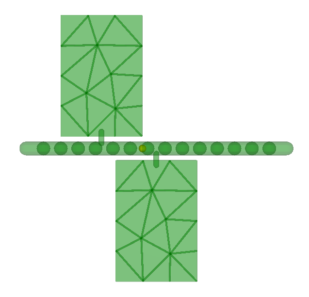
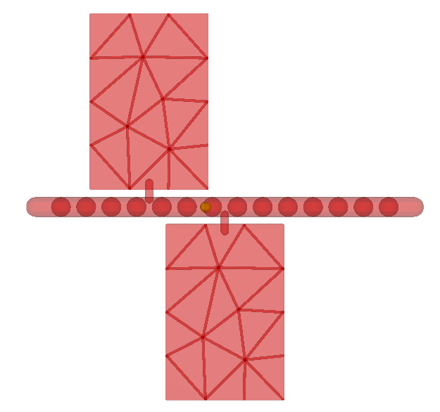
As it is a beta, this functionality has some limitations. For instance, it is not possible to create a joint between two rigid compound parts, and you have to make sure that there is at least one flexible element between each pair of flexible elements attached to a rigid part, in all directions. The figure below illustrates two different scenarios. In Figure 1.3: Example of correct condition for Flexible Particle Assembly you can see a scenario where we have at least one flexible element between two rigid parts, which is correct for the simulation. In the other hand, in Figure 1.4: Example of Inappropriate condition for Flexible Particle Assembly we have an example of an inappropriate condition. You can see that even though there is at least one flexible element between the rigid parts, Rocky considers a 10% upscaling tolerance that you have to take into account.
Note that if you have larger elements when compared to the rigid parts, the rigid parts upscaling will be less significative.
MULTI-ELEMENT (FLEXIBLE AND/OR DISCRETE-BREAKABLE) PARTICLE SHAPE LIMITATIONS
All Shell and Fiber particle shapes can be composed of Multiple Elements, which is also known as meshed. In the Solid particle shape category, however, only Polyhedron and Custom Polyhedron shapes support meshing. All other kinds of Solid shapes must be composed of only a single element (non-meshed).
Flexible particles-which are composed of Multiple Elements and are also known as meshed particles-can have only a single Size (Diameter or Scale Factor) defined per particle set. (This can also be known as a "monosized" particle.)
Shell and Solid particles composed of Multiple Elements (also known as meshed particles) are incompatible with Fluent CFD coupling, including the 1- and 2-Way Fluent options. The only meshed particle shapes compatible with these features are Fibers. (See also About Adding and Editing Particle Sets.)
Flexible particles-which are composed of Multiple Elements and are also known as meshed particles- do not support editing Rolling Resistance values. As a result, Rolling Resistance will always be set to zero (0) for these shapes.
Flexible particles-which are composed of Multiple Elements and are also known as meshed particles- also do not support editing Enable Rotations settings. As a result, Enable Rotations will always be turned on (enabled) for these shapes.
Flexible particles-which are composed of Multiple Elements and are also known as meshed particles- that are used for the analysis of any particle-related collisions statistics (see also About Inter-group Collision Statistics, About Intra-Particle Collision Statistics, or About Inter-particle Collision Statistics), will either ignore the effects of upscaling or will not include some properties and curves even when the Meshed Particles Upscaling checkbox is enabled. (See also About Meshed Particles Upscaling.)
Plasticity models are available only for Shell and Fiber particle shapes that are composed of Multiple Elements, which is also known as meshed. In this version of Rocky, plasticity models are not available for flexible Solid particles.
Particles composed of multiple elements (also known as meshed) are incompatible with Coarse Grain Modeling. This includes flexible Fibers, Shells, and Solids.
Particles composed of multiple elements (also known as meshed) are incompatible with the Flip Count property for Particles.
Every continuous injection Inlet must have its entry point set.
Every entry for a Volumetric Inlet must have a positive Mass value.
At least one Particle set or fluid within the continuous injection Inlet must have a mass flow rate value greater than 0 t/h.
Periodic continuous injections are incompatible with disabling the Release Particles Without Overlap Checks setting.
Volumetric Inlets require a minimum of 3 particles in order to create the "Seed". (You are not able to create a Volumetric Inlet with less than 3 particles.)
The three-way combination of a (1) Particle Custom Inlet that uses (2) frozen Fibers and also has a (3) Motion Frame assigned to it is, as a specific combination, incompatible with both Cartesian and Cylindrical Periodic Domains. (See also About Domain Settings Parameters.)
See Also:
The below list defines the various limitations and restrictions for setting Materials and its Interactions, in Rocky.
(Recommendation) Solid Materials should have a Poisson ratio in the recommended range (0.0 to 0.5).
Every entity that has solid materials (conveyors, geometries, and particles) must have a Solid Material set.
MATERIALS INTERACTIONS LIMITATIONS
A Materials Interactions' coefficient of restitution must be in the predefined range (0.1 to 1.0).
When using the Linear Adhesive Force (see also About Physics Parameters) for Materials Interactions, the Stiffness fraction between two materials must be in the range of [0.0 to 1.0).
When using the Constant Adhesive Force (see also About Physics Parameters) for Materials Interactions, the Force fraction between two materials must not be negative.
See Also:
The below list defines the limitations and restrictions for setting a fluid flow simulation using the SPH functionality in Rocky.
GENERAL LIMITATIONS FOR SPH SIMULATIONS IN ROCKY
Only one phase of SPH elements is supported per simulation.
Shell particles will only interact with SPH elements if the SPH element size is at least 4 times greater than the Shell particle thickness.
See Also:
The below lists define the various limitations and restrictions for using the 1-Way LBM method, the 1-Way Constant Coupling Method, and any Ansys Fluent simulations that are coupled 1-Way or 2-Way with Rocky.
1-WAY LBM COUPLING LIMITATIONS
Shell and Solid particles composed of Multiple Elements (also known as meshed, a model which can enable flexible and/or discrete-breakable particles) are incompatible with 1-Way LBM. The only flexible particle shapes compatible with this feature are Fibers. (See also About Adding and Editing Particle Sets.)
The Air Flow boundary box that you define through the three Coordinate Limits fields will interact with the flow of air just as would a solid wall geometry. For this reason, it is recommended that you increase the size of the air flow boundary box well beyond the area where you expect to see air flow interactions. (Note that increasing your Air Flow boundary size will also increase the processing time due to the additional amount of air flow cells that will need to be calculated.)
Setting a smaller Air Flow Cell Size than your largest particle can result in air flow vectors incorrectly appearing outside of the geometries that are supposed to contain them. For this reason, it is recommended that you select an Air Flow Cell Size at least as large as your largest particle size.
The 1-Way LBM coupling method is incompatible with Coarse Grain Modeling. (See also About Physics Parameters.)
1-WAY CONSTANT COUPLING LIMITATIONS
When combined with Coarse Grain models, only drag forces are considered. This means that other non-drag fluid force models, such as virtual mass and lift, are incompatible with Coarse Grain modeling.
Shell and Solid particles composed of Multiple Elements (also known as meshed, a model which can enable flexible and/or discrete-breakable particles) are incompatible with the 1-Way Constant method. The only flexible particle shapes compatible with this method are Fibers. (See also About Adding and Editing Particle Sets.)
1-WAY AND 2-WAY FLUENT COUPLING LIMITATIONS
CFD coupling simulations with Fluent (for both 1-Way and 2-Way) must have the same Thermal Model setting in both Rocky and Fluent. That is, both Rocky and Fluent must have thermal modeling either enabled or disabled. (See also Enable Thermal Modeling Calculations.)
When combined with Coarse Grain models, only drag forces are considered. This means that other non-drag fluid force models, such as virtual mass and lift, are incompatible with Coarse Grain modeling.
Shell and Solid particles composed of Multiple Elements (also known as meshed, a model which can enable flexible and/or discrete-breakable particles) are incompatible with the 1-Way Fluent and 2-Way Fluent methods. The only flexible particle shapes compatible with these methods are Fibers. (See also About Adding and Editing Particle Sets.)
In addition, Shell particles composed of Single Elements (also known as a "rigid" particle shape) are incompatible with both the 1-Way Fluent and 2-Way Fluent coupling methods.
The Ganser Drag Law is not supported for Assembly particle shapes.
See also the Coupling limitations section within the CFD Coupling Technical Manual. (From the Rocky Help menu, point to Manuals and then click CFD Coupling Technical Manual.)
2-WAY FLUENT COUPLING LIMITATIONS
2-Way Fluent coupled simulations with Remesh are not compatible with Sub-Stepping method.
See also the Coupling limitations section within the CFD Coupling Technical Manual. (From the Rocky Help menu, point to Manuals and then click CFD Coupling Technical Manual.)
2-WAY FLUENT AND 2-WAY FLUENT SEMI-RESOLVED COUPLING LIMITATIONS
Multiphase 2-Way Fluent simulations are not compatible with the Multi-Fluid VOF Model in Fluent. When setting up your Fluent case, ensure that all Eulerian Parameters are cleared on the Mutiphase Model dialog.
2-WAY FLUENT SEMI-RESOLVED COUPLING LIMITATIONS
2-Way Fluent Semi-Resolved simulations are not compatible with thermal modeling. (See also Enable Thermal Modeling Calculations.)
2-Way Fluent Semi-Resolved simulations work only with Spheres, Shells (either rigid or flexible), or Custom Imported Polyhedrons (rigid only). This method is not compatible with Fibers (neither rigid nor flexible), default Solids, nor flexible Custom Imported Polyhedron particle shapes. (See also Rocky Particle Shapes and Capabilities.)
The 2-Way Fluent Semi-Resolved method will not provide fluid-related properties for post-processing in Rocky. (See also About Properties.)
2-Way Fluent Semi-Resolved simulations do not work with the CFD Coupling Particle Statistics Module. (See also About the CFD Coupling Particle Statistics Module.)
2-Way Fluent Semi-Resolved simulations are not compatible with turbulent fluid flows.
2-Way Fluent Semi-Resolved simulations are not compatible with Assembly particle shapes.
Ansys Workbench integration with Rocky works only when linked with a geometry file from Ansys SpaceClaim. This means that using Rocky through Workbench will not work with the following scenarios:
No imported geometries. (I.e., Default Rocky conveyors only.)
Geometries imported into Rocky that are not linked through SpaceClaim.
Note: The Rocky-Workbench coupling is not available on Linux OS because of dependencies on the CAD reading file process by SpaceClaim.
(See also About Rocky and Ansys Workbench Integration.)
See Also:
The CFD Coupling Technical Manual document. (From the Rocky Help menu, point to Manuals and then click CFD Coupling Technical Manual.)
The below list defines the various limitations and restrictions for displaying Rocky and processing your simulations.
If the detected OpenGL version is older than 2.1, 3D rendering will be slow. This can happen, for instance, when accessing Rocky via Remote Desktop connections.
GPU simulations require a CUDA-enabled GPU.
If want to save for restart purposes a partially processed simulation with breakage enabled, be aware that any fragments that were in the simulation at the time you save the copy will not be present in the copied version due to incompatibilities with the features.
If you stopped a simulation that was in the middle of processing and later want to resume processing it using a newer version of Rocky, you may only resume if the simulation was last processed in the same major version of the product as the version you are using now. For example, if you started processing your simulation in version 4.1.0, you may resume processing it in any 4.1.x version released thereafter, but may not resume it in any version of the next major release of 4.2.x, and so on.
Multi GPU processing is incompatible with the Radl et al. Coarse Grain Model.
See Also:
The below list defines the various limitations and restrictions for the installed-by-default modules that come with Rocky.
COLLISION STATISTICS LIMITATIONS
With the exception of some Inter-particle Collision Statistics properties (see also About Inter-particle Collision Statistics), when analyzing the resulting properties or curves of most particle-related collisions statistics (see also About Inter-group Collision Statistics or About Intra-Particle Collision Statistics), the particle upscaling effects for Flexible particles-which are composed of Multiple Elements and are also known as meshed particles- will be ignored even when the Meshed Particles Upscaling checkbox is enabled. (See also About Meshed Particles Upscaling.)
CFD COUPLING PARTICLE STATISTICS LIMITATIONS
The 2-Way Fluent Semi-Resolved method does not currently support the CFD Coupling Particle Statistics Module. (See also About Using the 2-Way Fluent Semi-Resolved Method.)
See Also: