


Before you process a simulation, it is a good idea to check the key criteria provided on the Simulation Summary dialog. Doing this can help you catch data entry errors, and can help you get a rough estimate of how long the simulation might take to process.
At any point, you may also check the Summary tab on the Solver entity to gain access to the same information. From here, you can also see the Rocky version and simulation save dates for the project.
What would you like to do?
See Also:
Checking the key criteria listed on the Simulation Summary dialog (or tab) before you get too far into processing your simulation can help you catch data entry errors, which has the potential of saving you time in processing your simulation.
The Simulation Summary dialog automatically appears whenever you start a new simulation (see also Start Processing a Simulation from the Beginning). You can also view similar summary information after processing has started from the Solver entity. No matter whether processing has started or not, the Summary tab is also where you can find valuable timestamp information for the project, such as in what version of Rocky the project was created or last saved.
If you see information on the Summary that indicates that there might be an error in your setup-for example Number of Particles is higher than expected, Particles Breakage is turned on (marked as True) by mistake, and so on-you can either click Cancel on the dialog, which will stop the simulation from initialization; or if the dialog has already closed, you can click the Stop button on the Solver tab in the Data Editors panel. Both actions will stop the simulation from processing so that you can review and fix your setup information before continuing.
Besides helping you pin-point potential errors, the Summary information can also act as an indicator for how long it might take your simulation to process. While a higher Timestep Duration value will typically result in a faster simulation, for all other properties provided on the Simulation Summary, higher numbers and True values will generally result in longer simulation processing times. (See also Best Practices for Faster Processing). Tip:To get particle count estimate without having to start processing the simulation, you can also view the information on the Info tab of the Particle Inputs entity at any time during your project setup. For single-sized Particle sets, the counts provided on the Info tab will exactly match those provided on the Simulation Summary. For Particle sets with size distributions, the counts provided are estimates only and will differ from those on the Simulation Summary. (See also About the Info Tab). Use the figures and table below to understand the various types of summary information provided for simulations.
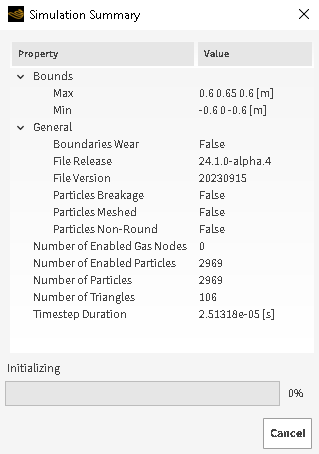
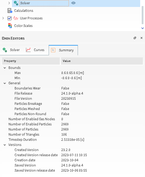
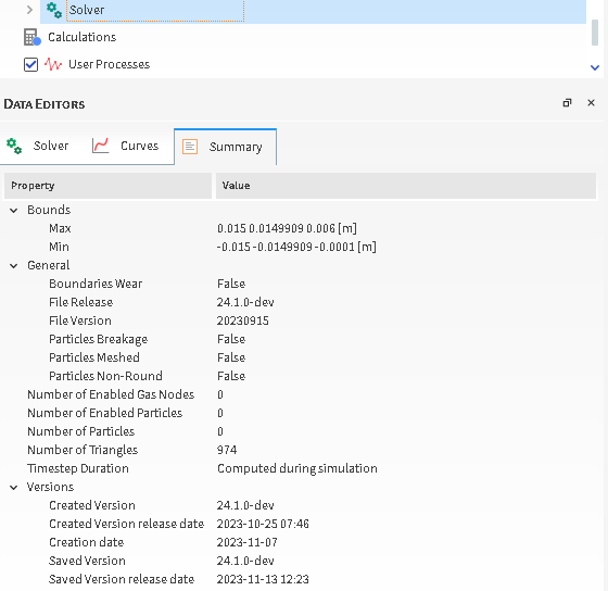
Table 1: Simulation Summary dialog and tab options
Property | Description |
|---|---|
Bounds | |
Max | The maximum coordinates for which geometry triangles are drawn. If Set as Boundary Limits is selected, once a particle reaches these limits, it will be removed from the calculations and will will disappear from any 3D Views. (This is done to save on processing power). (See also About Domain Settings Parameters). Note: Geometry limitations, including periodic domains, will also affect when particles enter and leave a simulation. |
Min | The minimum coordinates for which geometry triangles are drawn. If Set as Boundary Limits is selected, once a particle reaches these limits, it will be removed from the calculations and will disappear from any 3D Views. (This is done to save on processing power). (See also About Domain Settings Parameters). Note: Geometry limitations, including periodic domains, will also affect when particles enter and leave a simulation. |
General | |
Boundaries Wear | Indicates whether surface wear modification calculations are enabled (True) or not (False). (See also View Surface Wear Modification on an Imported Geometry). Note: Surface wear modification calculations take additional time to process. |
File Release | Number used to identify the name of the released Rocky version used to process the simulation project. |
File Version | Number used to identify the release date of the Rocky solver version that was used to process the original simulation project. Due to the way Rocky is programmed, this can be a different date than the date the Rocky program itself was released; knowing this date can be useful to Rocky support when troubleshooting simulation issues. The format of the date is YYYYMMDD with YYYY representing the four-digit year, MM representing the two-digit month, and DD representing the two digit day. |
Particles Breakage | Indicates whether particle breakage calculations are enabled (True) or not (False). (See also Enable Particle Breakage Calculations). Note: Breakage calculations take additional time to process. |
Particles Meshed | Indicates whether any of the particle sets are composed of multiple elements (True) or not (False). (See also About Adding and Editing Particle Sets). |
Particles Non-Round | Indicates whether shaped particles are simulated (True) or not (False). Note: Shaped particles take additional time to process when compared to Spheres. |
Number of Elements | For projects in which there are particle sets composed of multiple elements (see also About Adding and Editing Particle Sets), this lists the total number of elements that will appear in the simulation, from start to finish. For projects including particle sets composed of both single and multiple elements, each single-element particle will count as zero elements. |
Number of Enabled Elements | For projects in which there are particle sets composed of multiple elements (see also About Adding and Editing Particle Sets), this lists the total number of elements already present in the simulation at simulation onset. For most projects, this will be zero. Values higher than zero will be possible only for partially processed projects that have been saved for restart purposes. (See also Save a Copy of a Partially Processed Simulation for Restart Purposes). |
Number of Enabled Gas Nodes | When 1-Way LBM CFD Coupling calculations are turned on, this is the number of air nodes that will be used during the simulation. The number is calculated based on air flow cell size and air flow boundary limits. (See also Use the 1-Way LBM Method). |
Number of Enabled Particles | Total number of particles already present in the simulation at simulation onset. For most projects, this will be zero. Values higher than zero will be possible only for partially processed projects that have been saved for restart purposes. (See also Save a Copy of a Partially Processed Simulation for Restart Purposes). |
Number of Particles | Total number of whole particles that will appear in the simulation, from start to finish. The number is calculated based on particle size, mass flow rate, and density values, as well as inlet release times. (See also Add and Edit Particle Inputs). Note: This value includes whole particles only and does not take into account particle fragments nor elements. Tip: You can get a more detailed estimate of particle count at any time during simulation setup by viewing the Info tab for the Particle Input entities. (See also About the Info Tab). |
Number of Triangles | Total number of geometry triangles that will be used in the simulation. The number is either obtained from imported CAD geometry files or is calculated based on the Triangle Size value specified in the various settings dialogs for geometries. |
Timestep Duration | This critical value for ensuring the stability and accuracy of the simulation is automatically calculated based upon the particle size, density, bulk Young's Modulus, and restitution coefficients used in the simulation. Note: This number will change based upon simulation parameters. |
Versions (Summary Tab only) | |
Created Version | The Rocky version that was used to create (first save) the original project. |
Created Version release date | The release date and time of the Rocky version that was used to create (first save) the original project. |
Creation date | The date that the original project was created (first saved). |
Saved Version | The Rocky version that was used to save the latest version of the project. |
Saved Version release date | The release date and time of the Rocky version that was used to save the latest version of the project. |
What would you like to do?
See Also:
Ensure that you have set up the minimum requirements for processing. (See also Setting Up a Simulation.) Tip:Before processing, you can get an estimate on how many particles might be released into the simulation by viewing the Info tab for the Particle Input entities. (See also About the Info Tab.)
From the Data panel, select Solver and then from the Data Editors panel, click Start. The Simulation Summary dialog appears, which you can review while the simulation is automatically initialized.
Tip: The Simulation Summary dialog will close automatically when the simulation is fully initialized and begins processing. If the dialog closes too quickly for you to review it, you may review the same information on the Summary tab of the main Solver entity.
See Also:
Tip: This procedure can be followed only after a simulation has begun processing.
From the Data panel, select Solver and then from the Data Editors panel, select the Summary tab.
Review the information provided.
See Also:
This task is especially useful when you are trying to determine what version of your project is the latest, or when you need to know with what version of Rocky the original project was created. Knowing the latter can help you determine what Rocky features and functionality are available for the project.
Tip: This procedure can be followed at any point during or after simulation setup and processing.
From the Data panel, select Solver and then from the Data Editors panel, select the Summary tab.
Under Versions, review the information provided.
See Also: