


What kind of problem are you having?
I am having difficulty properly calibrating sticky, wet, or cohesive particles
I cannot find the upper limit for importing custom particles shapes
I entered an invalid variable or value and Rocky accepted it
Rocky does not list my Ansys version when I try to set up 2-Way Fluent Coupling
I get "reference" errors in my Motion Frames when I open an older project
I get an "Unsupported Particle" error when I open an older project
I Cannot Find the Movements Tab for My Older Simulation Projects
I cannot figure out how to set the Parent Reference for a Motion Frame
I get "Displacement" errors in my Motion Frames when I open an older project
I cannot enter an input variable or mathematical function into a text field
I cannot find the Set Contact Detection Neighboring Distance parameter
I cannot find the Maximum Volume Fraction Target parameter for 2-Way Fluent
See Also:
The import scale cannot be changed once the geometry files have been imported. To change the scale, you must replace the geometry file and then change the scale on re-import. (See also Replace an Imported Geometry File.)
See Also:
If you are unable to change the setup parameters of your project, then you have most likely already begun to process the simulation. Once you click Start on the Solver tab, you cannot change the setup parameters without losing the simulation results that have already been calculated. This is because the setup parameters directly affect the calculations that Rocky is solving.
If you must change the parameters after you have started processing the simulation, first stop the simulation (see also Stop a Simulation from Processing), change your setup parameters, and then start your simulation over from the beginning (see also Start Processing a Simulation from the Beginning.).
See Also:
In this version of Rocky, there are two kinds of APIs:
API:PrePost, which are used to create PrePost Scripts for the purpose of automating many setup and post-processing tasks.
API:Solver, which are used along with the Rocky Software Development Kit (SDK) to make your own custom modules.
See sections below for more information.
Information about API:PrePost functionality can be found in two places: in the API:PrePost Manual and in the Python Shell.
Many common setup and post-processing APIs are documented in the API:PrePost Manual (Figure 1). (From the Rocky Help menu, point to Manuals and then click API:PrePost Manual).
Once the API:PrePost Manual open, use the Contents, Index, or Search tabs in the Help viewer to find the APIs you need.
Important: Not all Rocky API:PrePost functionality is currently documented in the API:PrePost Manual; there are additional APIs available for some Rocky post-processing features that are documented in the Rocky code itself. These can be accessed via the Python Shell.
The API:PrePost functionality documented in the API:PrePost Manual, plus additional post-processing scripts not covered in the manual, are available in the Python Shell panel. (See also Customize and Extend Rocky with Python.)
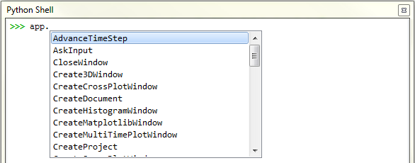
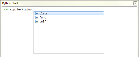
For example, type app. into the Python Shell panel and then press Enter to see a list of what application-level PrePost APIs are available (Figure 2). If you then select an item from that list and then press ., another list of commands you can apply to that item appears (Figure 3), and so on.
If you need additional assistance creating your PrePost Scripts, please Submit a Support Request.
Figure 8.2: List of application-level API:PrePost functionality available for use in your PrePost Scripts
Information about API:Solver functionality can be found in the API:Solver Manual. (From the Rocky Help menu, point to Manuals, and then click API:Solver Manual.)
See Also:
Currently, Ansys Fluent is the only program supported by Rocky for CFD Coupling purposes. This is especially true of Two Way Coupling. (See also About Using the 2-Way Fluent Method.)
However, if your CFD program is configured to the same format as Fluent, it might be possible for Rocky to accept another program's CFD data during a 1-Way Fluent process. (See also About Using the 1-Way Fluent Method.)
See Also:
Sticky, wet, and otherwise especially cohesive particles can be difficult to properly calibrate.
You may wish to use the Material Wizard and/or the Calibration Suite to help you in this process. These automated solutions can help you quickly and easily determine more accurate DEM parameters to more realistically represent your target materials.
If you are interested in learning more about how the particle-to-particle and particle-to-boundary contact forces are calculated, refer to the DEM Technical Manual. (From the Rocky program Help menu, point to Manuals, and then click DEM Technical Manual.)
It is quite possible to simulate different types of magnetic forces in Rocky by adjusting the Adhesive Force (see also About Physics Parameters) and various material-to-material properties, including the Adhesive Distance of your particle-to-particle and/or particle-to-boundary interactions.
See Also:
High Pressure Grinding Rolls (HPGRs) are comminution devices that are simulated in Rocky using breakage modeling. Use the following resources to help you get started simulating an HPGR device:
See a video example of an HPGR simulation here: Rocky DEM - Showing Particle Breakage in HPGR Mill
Walk step-by-step through setting up an processing an HPGR simulation here:
Tutorial - High Pressure Grinding Roll (HPGR) in the Rocky Tutorial Guide
See Also:
Each custom particle shape that you import counts as one separate Particle set, and there is no limit to the number of unique Particle sets you can add per simulation project.
See Also:
Most Rocky fields enable you to enter variables and/or mathematical functions instead of direct, numerical values. (See also Enter Input Variables or Mathematical Functions as Parameter Values.)
Because this parametric variables ability enables you to change the value of any field making use of an input variable at any point during your project setup, Rocky is not able to pre-limit the values you enter to only accept valid entries. Rather, Rocky notifies you of invalid entries afterward through either a dialog or Status panel warning (see also Double-Click the Status Panel to Jump to the Appropriate UI Location).
Therefore, it is best to follow the Range column provided for the parameter's definition in Rocky Help (this document) and heed the warnings in the Status panel rather than assuming that if Rocky accepts the value, it is valid for your simulation setup.
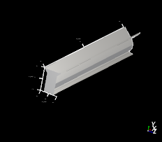
For example, Rocky will allow you to set the Troughing Angle parameter for a receiving conveyor (with a Belt Profile equal to two or more rolls) to any value even though some values make less sense than others, and others are simply invalid, as illustrated in Table 1.
Table 1: Example results when different Troughing Angles are provided for receiving conveyors with two or more belt profiles
Troughing Angle Value | Results Description | Results Image |
|---|---|---|
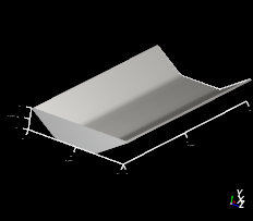
35 degrees (default value) | Valid entry produces a troughed belt that will hold material. |
|
0 (zero) degrees | Invalid entry produces no belt. |
|
135 degrees | Valid but useless entry produces a folded over belt that will hold no material. |
|

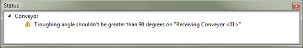
Rocky Help defines the Range for this Troughing Angle parameter as "0 < 90 degrees", which can help guide you before you enter your values. And if you do enter a value outside of this range, the following Status panel warnings are presented:
Figure 8.4: Warning provided in Status panel when Troughing Angle value is above the recommended maximum
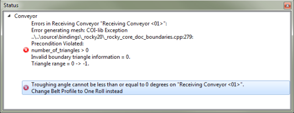
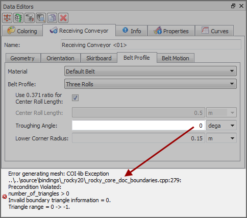
In addition, when a 3D View window is open, some errors are also presented at the bottom of the Data Editors panel:
See Also:
Enter Input Variables or Mathematical Functions as Parameter Values
About Receiving Conveyor Parameters
About Feed Conveyor Parameters
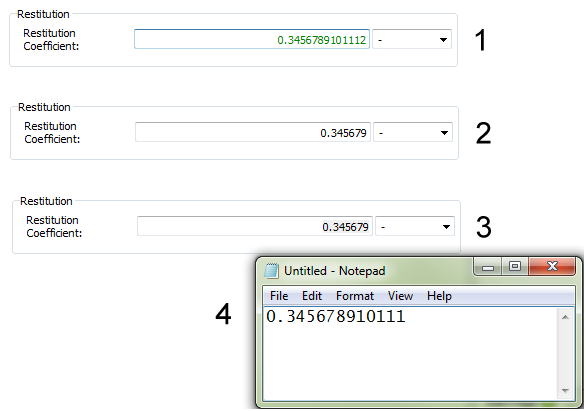
When displaying calculated values in text fields, Rocky keeps long, very precise numbers as an internal value but will truncate what is displayed in the UI to only six decimal places. When you copy (Ctrl + C) a value like this, the full internal value is the one copied to your clipboard and not the truncated version.
This means that if you then paste the copied value into another program, you will see the full, untruncated value. However, if you paste it into another field in Rocky, you will briefly see the full, untruncated value but then when you click away from that field, Rocky will truncate it to six decimal places again.
In the example shown in Figure 1, a very precise value is entered with 13 numbers after the decimal place (1). After clicking away from the text field, that precise value is truncated to only 6 numbers after the decimal place (2). However, if you select and copy that truncated value (3), and then paste it into a program outside of Rocky (4), you get the full internal value with all the decimal places.
Figure 8.7: Example of a long number (1) truncated (2), copied (3), and then pasted outside of Rocky (4)
See Also:
When setting periodic Cartesian domains (previously known as "periodic boundaries"), it is important to set the distance between the Min Coordinate and Max Coordinate values to at least 2.5 times wider than your largest particle size. Or, alternatively, ensure that your largest particle size is less than 0.4 times the width of your periodic Cartesian domain.
If you set the width of the periodic domain smaller than this, you will see the following error message after starting to process your simulation.
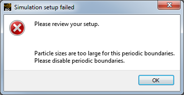
To solve this issue, click OK and then change your periodic Cartesian domain's Min Coordinate and Max Coordinate values, and/or your particle sizes, to be inline with the guidelines above.
See Also:
In Rocky, rendering and lighting-both of which are used to display 3D items in view windows-do not always work well with items that are very small in scale. This is not usually an issue with 3D Views because the scale of your geometries is typically large enough to prevent these kind of issues.
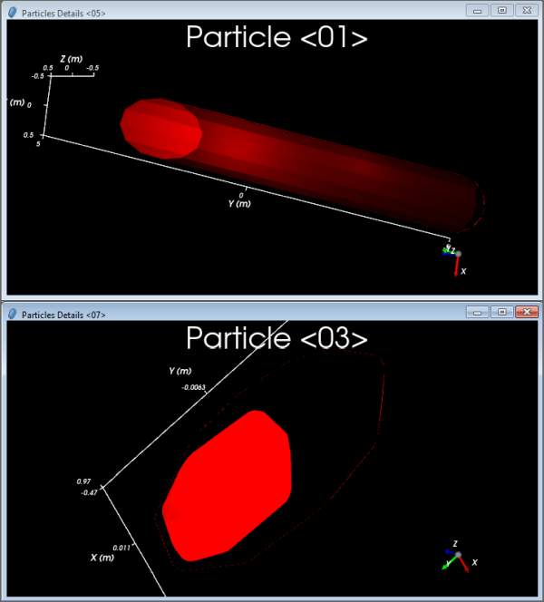
It can be an issue, however, when previewing very small particle shapes in a Particles Details window. This is because the display of the shape is linked to the size of the particle. Especially when going from a (relatively) large particle size display to a very small one in the same window, zooming in on the resulting much smaller particle may result in a display that cuts off part of the particle, and/or makes certain particle areas transparent in unusual ways (Figure 1).
Figure 8.9: Example of a small-scale straight fiber (above) and a small-scale sphero-polyhedron (below) displaying rendering and lighting issues in the Particles Details window
If this happens, reset the view by doing one of the following:
Press the R key on your keyboard or press the Fit button on the toolbar to fit the active components into view
Close the current Particles Details window and open a new one
See Also:
In order to list the Ansys versions available for 2-Way Fluent coupling, Rocky needs information about the Ansys installation. Rocky follows a particular order when making that determination, and that order differs slightly depending upon whether your installation is on a Linux- or Windows-based machine. See below for further details and possible solutions.
On both Windows- and Linux-based machines, Rocky first expects a variable to be provided called
AWP_ROOTXXX, whereXXXrefers to the particular Ansys version. Rocky expects this variable to point to the root folder of the AWP folder. For example:On Windows-based machines, this variable for Ansys version 19.0 could point here:
C:Program FilesANSYSv190Tip:On Windows machines, this variable should have been added during the Ansys installation process.On Linux-based machines, this variable for Ansys version 19.0 installed for "user" could point here:
/home/user/ansys/v190
If the
AWP_ROOTXXXvariable is not provided as expected, then the following steps are taken:On Windows-based machines, Rocky does nothing further.
On Linux-based machines, Rocky takes the following steps in the order provided:
Rocky expects a different variable to be provided called
ANSYSXXX_DIR, whereXXXrefers to the particular Ansys version. Rocky expects this variable to point to the ansys folder inside of the AWP folder. For example:/home/user/ansys/v190/ansysIf the
ANSYSXXX_DIRvariable is not provided as expected, then Rocky looks for the Ansys installation files in the locations and order listed:Inside the version folder of the
ansys_incfolder. For example,/ansys_inc/v190Same folder as before but inside the
Usrfolder. For example,/usr/ansys_inc/v190
If when you are setting up a 2-Way Fluent coupling simulation, Rocky does not list the Ansys version you have installed on your machine, start by checking if any of the options above exist (paths or variables).
If you find they do not exist, then Rocky does not know where Fluent is installed and cannot recognize whether it is valid for 2-Way Fluent coupling. You can try solving this by creating an environmental variable as suggested above, or by reinstalling Ansys on your machine.
See Also:
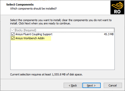
If when you open Ansys Workbench, you do not see the Particle Dynamics (Rocky) component listed under Analysis Systems in the Toolbox panel, it is likely that you do not have the Ansys Workbench Addin installed. In this version, the only way to install this addin is to re-install Rocky.
During the re-installation process, ensure that you keep the Ansys Workbench Addin checkbox selected (Figure 1).
See Also:
In versions of Rocky prior to v4.4, there was a Reference setting that allowed one of several values (Parent, Local, or Global, depending upon the Rocky version) to be set on an individual motion or Frame (depending upon the Rocky version). In this version of Rocky, the Reference setting has been removed. This means that all motions within a Frame are always based upon what was previously known as the "local" reference.
Because of these changes, if you open a project created prior to Rocky v4.4 that had either different motion-based References set for one Frame, or had either Global or Parent References set for either frames or individual motions, you will receive special errors in the Data panel (Figure 1).
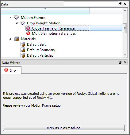
These errors are meant to communicate that the older project you opened has reference values set that are no longer supported in this newer version, and Rocky needs you to verify that the new Frame-based local-only reference settings are as you want them before continuing.
From the Data panel under Motion Frames, select the Frame over which the error appears.
From the Data Editors panel, ensure that the motion settings are as you want. Important As you review the settings, keep in mind that all motions within the Frame are now based only on an implicit "local" reference. Tip:You can recreate similar "parent" reference behavior by using nested Frames. See also I cannot figure out how to set the Parent Reference for a Motion Frame.
Once you have ensured that the settings are as you want, from the Data panel, select the error and then from the Data Editors panel, click the Mark issue as resolved button. The error is removed.
Note: You must address these errors before you can process your simulation.
See Also:
The Collect Forces to FEM Analysis checkbox used to be on the Solver | General tab but with the inclusion of the new Boundary Collision Statistics feature, is now enabled in that location via the Forces for FEM Analysis checkbox.
See Also:
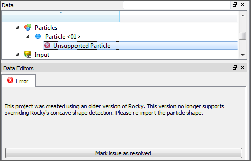
In previous versions of Rocky, you were allowed to mark a particle shape as convex even though Rocky determined it to be concave. Overriding this determination is no longer supported in newer versions of Rocky. Therefore, when you open an older project where the concavity of the particle shape was overridden, you will see an "Unsupported Particle" error associated with the Particle set (Figure 1).
To solve this issue, you will need to re-import the shape, and then mark the issue as resolved by clicking the Mark issue as resolved button.
If after re-importation, Rocky determines the shape to be concave but you still want Rocky to calculate it as convex, you will be given the option of having Rocky re-draw the particle to meet the latest shape requirements. (See also About Defining and Importing Custom Particle Shapes.)
See Also:
In prior versions of Rocky, there was a feature on the Solver | Collisions tab known as Particle Collision Statistics. In this version of Rocky, that feature is now known as Intra-particle Collision Statistics and is now enabled from a Module with that same name.
See Also:
In previous versions of Rocky, there was an Experimental (Beta) Feature for CFD Coupling called Particle Size Scale Factor. In this version of Rocky, that setting has been removed and replaced with a new Coarse Grain Modeling setting called CGM Scale Factor. This new parameter can be found on the Size tab for a Particle set when Coarse Grain Modeling is enabled. (See also About Adding and Editing Particle Sets.)
Note: Older Rocky simulations that made use of the prior Particle Size Scale Factor may not work the same in this version of Rocky. It is recommended that for these older simulations, you enable Coarse Grain Modeling, make use of the new CGM Scale Factor setting, and then re-process your simulation.
See Also
In previous versions of Rocky, there was an Adhesive Force (on the Physics | Momentum tab) called Leeds.
As of the Rocky v4.4 release, the Leeds Adhesion model has been removed from the Rocky product and converted into an external module, which is installed separately via a ZIP file.
To make use of the Leeds Adhesion model, you must gain access to and then install this external module. Specifically:
To gain access to the module, visit the Rocky API:Solver - Modules page on the Ansys Learning Hub (https://jam8.sapjam.com/wiki/show/QOEdJpEQxxGLCRuqG6c1TY?_lightbox=true), scroll down to the Leeds contact model section, and then click the download link for the type of download you require.
To install the module once you have access to it, refer to the Install an External Module topic.
See Also:
In previous versions of Rocky, you could set an Inlet's Start and Stop Time, as well as define periodic release criteria on a separate "Simulation Configuration" sub-tab for the Inlet.
As of Rocky v4.4, these same "Simulation Configuration" parameters have been moved to the Continuous Injection Input. This means that you will now set these parameters per Entry Point that you define, which includes both Inlets and any default Feed Conveyors you have added to your simulation.
See Also:
About Inlet Parameters
About Feed Conveyor Parameters
Simulation projects created in versions of the software prior to Rocky 4 were able to define custom (imported) geometry motions by using a Movements tab in the Data Editors panel. Opening these older simulation projects in Rocky versions 4.0.0 - 4.3.x would retain the ability to still use these older movements even though the Motion Frames feature was created to replace this older functionality.
As of Rocky v4.4, these older movements are no longer supported. If you happen to open an older simulation project that had movements defined, you will now need to re-define those motions using the Motion Frames feature.
See Also:
In previous versions of Rocky, it was possible to set the reference for a Motion Frame to either "local" or "parent". When a parent reference was selected, the next motion for the Frame was based not upon the current orientation of the Frame, but upon the original orientation of the Frame when the motion started, relative to the current position of its parent Frame (if it was a child Frame) or the Global Coordinate System (if the Frame had no parent).
In this version of Rocky, all Frames are now implicitly based only upon what was once known as the "local" reference, which uses the current orientation of the selected Frame to define the next movement. In this way, the reference is always moving along with the Frame.
Important When opening a project created in an older version of Rocky, any Frames with references set to "parent" will now act only as "local". See also I get "reference" errors in my Motion Frames when I open an older project.
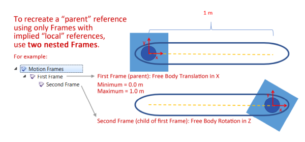
In this version of Rocky, you can recreate this "parent" reference behavior by creating a nested (child) Frame underneath another Frame (parent).
For example, in Figure 1 the First Frame (parent) contains a translation motion, and the Second Frame nested beneath it (child) contains a rotation motion. When the child Frame is assigned to a geometry, the rotation (child) motion will move relative to the current position of the translation (parent) motion.
See Also:
In versions of Rocky prior to v4.4, you were able to set "Keep in place" or "Displace with movement" options for certain motions within a Motion Frame. This meant that it used to be possible to have a Frame with both motions that were kept in place and others that displaced. In this version of Rocky, displacement is set only once for the entire Frame.
Because of these changes, if you open an older project containing a Frame with individual motions that had both "keep in place" and "displace with motion" options set, you will receive a special error in the Data panel (Figure 1).
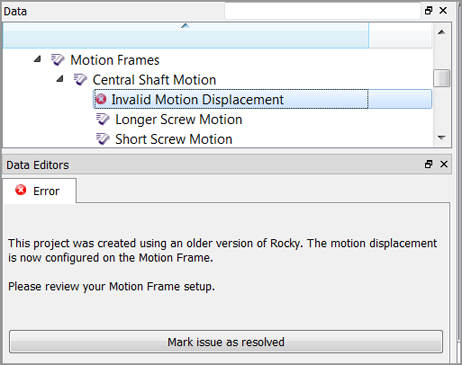
This error is meant to communicate that the older project you opened had mixed displacement settings that are no longer supported in this newer version, and Rocky needs you to verify that the new Frame-based displacement settings are as you want them before continuing.
From the Data panel under Motion Frames, select the Frame over which the error appears.
From the Data Editors panel, ensure that the motion settings are as you want. Important As you review the settings, keep in mind that all motions within the Frame will now share only one kind of displacement option.
Once you have ensured that the settings are as you want, from the Data panel, select the error and then from the Data Editors panel, click the Mark issue as resolved button. The error is removed.
Note: You must address these errors before you can process your simulation.
See Also:
If you are using the 1-Way LBM CFD Coupling method, you may have noticed that the parameter known in versions prior to v4.5.0 as Air Viscosity is now known as Air Kinematic Viscosity. In addition, the default units have changed from Pascal seconds (Pa⋅s) to square meter per seconds (m:sup:2/s) even though the default value has stayed the same.
While the default value of 1.5e-05 was correct for kinemetic viscosity, which is how Rocky actually uses this parameter, the units were incorrectly listed, which gave the false impression that this parameter represented dynamic viscosity.
Therefore, if based on the incorrect units, you misunderstood this parameter to be dynamic viscosity, you might have changed the default value for air viscosity to 1.8e-05 Pa⋅s. This value, while correct for dynamic viscosity, is not correct for kinemetic viscosity, which is how Rocky actually interprets it.
Since the numerical values for air are very close by both measures of viscosity (1.8e-05 Pa⋅s vs. 1.5e-05 m2/s at 20 °C), this error is unlikely to have affected your simulations. But in cases where exact values of air viscosity are required, or in cases where you are comparing LBM results from different Rocky versions, please be aware that adjustments might need to account for this change.
See Also:
Most text fields in Rocky support entering variables or mathematical functions as parameter variables, including three-part text fields. (See also Enter Input Variables or Mathematical Functions as Parameter Values.)
There are several text fields where parametric variables are currently not supported, however. These are listed in the table below.
Table 1: Text fields for which entering variables or mathematical functions are not supported
Text Field for which Parametric Variables are Disabled | Where Located | See Also |
|---|---|---|
Size | Under Custom Size on the Particle | Info tab for an individual Particle set. | |
Maximum Iterations | When the Advanced Features checkbox is enabled, this is located on the 2-Way Fluent | Coupling tab for 2-Way Fluent CFD Coupling. | |
Solver Processes | On the 2-Way Fluent | Fluent tab for 2-Way Fluent CFD Coupling. | |
Files to keep | On the 2-Way Fluent | Fluent tab for 2-Way Fluent CFD Coupling. | |
Contact Stiffness Multiplier | When the Advanced Features checkbox is enabled, this is located under Momentum on the Materials Interactions tab for a material-material pair. | |
Close Packing Volume Fraction | Under Coarse Grain Modeling on the Physics | Coarse-Graining tab. | |
Solver Curves | Under Output Frequencies on the Solver | Time tab. | |
Rendering Scale | On the Particles tab for the Windows Editors panel when the main 3D View entity is selected. | About Using the Window Editors Panel to Change All 3D Views in the Project |
See Also:
In previous versions of Rocky, if you enabled the Experimental (Beta) Features checkbox on the Options | Preferences dialog (see also About Setting Global Preferences), there was an Adhesive Force model (on the Physics | Momentum tab) called Velocity Dependent.
As of the Rocky v4.5 release, the Velocity Dependent Adhesion model has been removed from the Rocky product. If you want to simulate an older project that made use of this model, you must select a different Adhesive Force model before you will be able to process it.
See Also:
In prior versions of Rocky, you could define a Torque Law for your 1-Way Constant particle-fluid interactions. (See also About Using the 1-Way Constant Method.) However, the 1-Way Constant calculations did not actually make use of the Torque Law setting, so as of Rocky v4.5.0, this setting has been removed.
You are still able to define a Torque Law for 1-Way Fluent simulations. (See also About Using the 1-Way Fluent Method.)
See Also:
In previous versions of Rocky, there was a parameter on the Solver | Time tab called Output Frequency. In this version of Rocky, that parameter is now called Simulation and is located under the Output Frequencies section.
See Also:
In previous versions of Rocky, there was a parameter on the Solver | Time tab called Loading N-Steps. In this version of Rocky, that parameter has been re-classified as an advanced parameter, and is now located on the Solver | Advanced tab.
Note: The Advanced tab only appears when the Advanced Features checkbox is enabled on the Additional Features tab of the Options | Preferences dialog. (See also About Setting Global Preferences.)
See Also:
In previous versions of Rocky, there was a parameter on the Solver | Advanced tab called Set Contact Detection Neighboring Distance. This parameter enabled you to set only a single Neighboring Distance value for both particle-to-particle and particle-to-boundary contacts.
In this version of Rocky, you can now set unique Neighboring Distance values for each type of contact:
For particle-to-particle contacts, this new parameter is called Set Contact Detection Neighboring Distance between Particles.
For particle-to-boundary contacts, this new parameter is called Set Contact Detection Neighboring Distance between Particles and Triangles.
Note: The Advanced tab only appears when the Advanced Features checkbox is enabled on the Additional Features tab of the Options | Preferences dialog. (See also About Setting Global Preferences.)
See Also:
In previous versions of Rocky, if you had installed the Ansys Fluent Coupling Support item (see also Install Ansys Coupling Components), you could choose to export data out of Fluent through an Export Solution to Rocky menu item that was located within Fluent.
In this version of Rocky, this menu item has been replaced with another, more expansive Rocky Export menu in Fluent. Refer to the About Using the 1-Way Fluent Method topic for more information.
See Also:
In prior versions of Rocky, when the Advanced Features setting was enabled, you could define the Maximum Volume Fraction Target when you selected Volumetric Diffusion as your Mapping Method for your 2-Way Fluent simulations. (See also About Using the 2-Way Fluent Method.) However, this parameter was renamed to Solids Maximum Volume Fraction Target to help clarify that this setting pertains to the solids (particles) only, and not to the fluids.
See Also: