


Introduction
This analysis enables you to determine the response of structures to vibration loads that are random in nature. An example would be the response of a sensitive electronic component mounted in a car subjected to the vibration from the engine, pavement roughness, and acoustic pressure.
Loads such as the acceleration caused by the pavement roughness are not deterministic, that is, the time history of the load is unique every time the car runs over the same stretch of road. Hence it is not possible to predict precisely the value of the load at a point in its time history. Such load histories, however, can be characterized statistically (mean, root mean square, standard deviation). Also random loads are non-periodic and contain a multitude of frequencies. The frequency content of the time history (spectrum) is captured along with the statistics and used as the load in the random vibration analysis. This spectrum, for historical reasons, is called Power Spectral Density or PSD.
In a random vibration analysis since the input excitations are statistical in nature, so are the output responses such as displacements, stresses, and so on.
Typical applications include aerospace and electronic packaging components subject to engine vibration, turbulence and acoustic pressures, tall buildings under wind load, structures subject to earthquakes, and ocean wave loading on offshore structures.
Points to Remember
The excitation is applied in the form of Power Spectral Density (PSD). The PSD is a table of spectral values vs. frequency that captures the frequency content. The PSD captures the frequency and mean square amplitude content of the load’s time history.
The square root of the area under a PSD curve represents the root mean square (rms) value of the excitation. The application computes this value using the linear trapezoidal rule. The unit of the spectral value of acceleration, for example, is G2/Hertz.
The input excitation is expected to be stationary (the average mean square value does not change with time) with a zero mean.
This analysis is based on the Mode Superposition method. Hence a modal analysis that extracts the natural frequencies and mode shapes is a prerequisite.
This feature covers one type of PSD excitation only- base excitation.
The base excitation could be an acceleration PSD (either in acceleration2 units or in G2 units), velocity PSD or displacement PSD.
The base excitation is applied in the specified direction to all entities that have a Fixed Support boundary condition. Other support points in a structure such as Frictionless Surface are not excited by the PSD.
Multiple uncorrelated PSDs can be applied. This is useful if different, simultaneous excitations occur in different directions.
If stress/strain results are of interest from the random vibration analysis then you will need to request stress/strain calculations in the modal analysis itself. Only displacement results are available by default.
Postprocessing:
The regular results output by the solver for the Random Vibration analysis, such as Directional Deformation, are by default one sigma values, or one standard deviation values (with zero mean value). These results follow a Gaussian distribution. The interpretation is that 68.3% of the time the response will be less than the standard deviation value. One sigma is indicated by the Scale Factor property. All other result are not one sigma values. If you create a User Defined Result using the Solution Quantities and Result Summary Worksheet that is not a one sigma value, you will receive informational message indicating the situation.
Note:Currently, one sigma supports the following Expressions for User Defined Results:
UX/UY/UZ EPELX/EPELY/EPELZ EPELXY/EPELYZ/EPELXZ SX/SY/SZ SXY/SYZ/SXZ SEQV SPSD The use of the Scale Factor property is not supported for force-based results, such as FX/FY/FZ, even though these forces are considered one sigma in the Mechanical APDL application.
You can scale the result by 2 times to get the 2 sigma values. The response will be less than the 2 sigma values 95.45% of the time and 3 sigma values 99.73% of the time.
The Coordinate System setting for result objects is, by default, set to and cannot be changed because the results only have meaning when viewed in the solution coordinate system.
Since the directional results from the solver are statistical in nature they cannot be combined in the usual way. For example the X, Y, and Z displacements cannot be combined to get the magnitude of the total displacement. The same holds true for other derived quantities such as principal stresses.
A special algorithm by Segalman-Fulcher is used to compute a meaningful value for equivalent stress.
Preparing the Analysis
Create Analysis System
 Basic general information about this topic
 ... for this analysis type:
Because a random vibration analysis is based on modal responses, a modal analysis is a required prerequisite. The requirement then is for two analysis systems, a modal analysis system and a random vibration analysis system that share resources, geometry, and model data.
From the Toolbox, drag a Modal template to the Project Schematic. Then, drag a Random Vibration template directly onto the Modal template.
Define Engineering Data
Basic general information about this topic
... for this analysis type:
Both Young's modulus (or stiffness in some form) and density (or mass in some form) must be defined in the modal analysis. Material properties must be linear but can be isotropic or orthotropic, and constant or temperature-dependent. Nonlinear properties, if any, are ignored.
Attach Geometry
Basic general information about this topic
... for this analysis type:
There are no specific considerations for a random vibration analysis.
Define Part Behavior
Basic general information about this topic
... for this analysis type:
You can define rigid bodies for this analysis type.
Define Connections
Basic general information about this topic
... for this analysis type:
Only linear behavior is valid in a random vibration analysis. Nonlinear elements, if any, are treated as linear. If you include contact elements, for example, their stiffnesses are calculated based on their initial status and are never changed.
Only the stiffness of springs is taken into account in a random vibration analysis.
Apply Mesh Controls/Preview Mesh
Basic general information about this topic
... for this analysis type:
There are no specific considerations for a random vibration analysis.
Define Initial Conditions
Basic general information about this topic
... for this analysis
type:
A specific Modal Environment must be set as an initial condition/environment for the analysis to be solved.
Note: The modal analysis must extract enough modes to cover the PSD frequency range. Ansys recommends that you extract enough modes to cover 1.5 times the maximum frequency in the PSD excitation.
In order to process the PSD solution, the application creates additional solver files from the upstream modal analysis. Therefore, to create these required files, you need to solve the upstream Modal analysis before you can solve the PSD analysis. See the Analysis Data Management section for more information.
Establish Analysis Settings
Basic general information about this topic
... for this analysis type:
For a Random Vibration analysis the basic Analysis Settings include:
- Options for Analyses
You use this category to specify the number of modes to use from the modal analysis. Ansys recommends that you include modes that cover 1.5 times the maximum frequency in the PSD excitation table. You can also exclude insignificant modes by setting the Mode Significance Level property to between 0 (all modes selected) and 1 (no modes selected).
Note: If you set the Mode Significance Level property to
0.0, the application considers all modes in mode superposition of random vibration responses. This can require significant computation time for large systems that use a large number of modes to obtain random vibration displacement responses.In this case, a Mode Significance Level setting that excludes insignificant modes from superimposing random vibration displacement responses is recommended. However, this performance improvement reduces solution accuracy. As a result, you need to use caution and carefully check your solution. Set the Mode Significance Level to
1e-4when you are concerned about solution processing time. During Random Vibration analyses, the velocity and acceleration responses are separate calculations, in addition to displacement responses.To further improve your solution time, do not request velocity and acceleration responses unless needed. The velocity and acceleration responses require approximately the same computation time.
- Output Controls
By default, Displacement is the only response calculated. To include velocity (Calculate Velocity property) and/or acceleration (Calculate Acceleration property) responses, set their respective Output Controls to . By default, modal results are removed from result file to reduce its size.
To keep modal results from an upstream system, set the Keep Modal Results property to .
Note:
If your Random Vibration system is linked to an upstream Modal analysis and you plan to send Modal data to a downstream Sherlock (Post) system, you need to set the Keep Modal Results, Calculate Velocity, Calculate Acceleration properties to .
You can change the default setting of these properties using the Options dialog. See the Specifying Application Defaults and Preferences section of the Help under the Analysis Settings and Solution category for the specific options.
- Damping Controls
Damping Controls enable you to specify damping for the structure in the Random Vibration analysis. Controls include: Constant Damping, Damping Ratio, Stiffness Coefficient (beta damping), and a Mass Coefficient (alpha damping). They can also be applied as Material Damping using the Engineering Data tab. A non-zero damping is required. The Damping Ratio has a default setting of 0.01. This value can be modified by setting the Damping property to .
Note: For a Random Vibration system, if you choose the setting for the Constant Damping property and do not define damping for one of the above controls, the solver uses a default damping value of
0.01.- Analysis Data Management
These settings enable you to save solution files from the Random Vibration analysis. The default behavior is to only keep the files required for postprocessing. You can use these controls to keep all files created during solution or to create and save a Mechanical APDL application database (db file).
Note: The Inertia Relief option (under Analysis Settings) for an upstream Static Structural analysis is not supported in a Random Vibration analysis.
Apply Boundary Conditions
Basic general information about this topic
... for this analysis type:
Any Support Type boundary condition must be defined in the prerequisite Modal Analysis.
The only applicable load is a PSD Base Excitation of spectral value vs. frequency.
Remote displacement cannot coexist with other boundary condition types (for example, fixed support or displacement) on the same location for excitation. The remote displacement will be ignored due to conflict with other boundary conditions.
Four types of base excitation are supported: PSD Acceleration, PSD G Acceleration, PSD Velocity, and PSD Displacement.
Each PSD base excitation should be given a direction in the nodal coordinate of the excitation points.
Multiple PSD excitations (uncorrelated) can be applied. Typical usage is to apply 3 different PSDs in the X, Y, and Z directions. Correlation between PSD excitations is not supported.
Solve
Basic general information about this topic
... for this analysis type:
Solution Information continuously updates any listing output from the solver and provides valuable information on the behavior of the structure during the analysis. In addition to solution progress you will also find the participation factors for each PSD excitation. The solver output also has a list of the relative importance of each mode in the modal covariance matrix listing.
Note: When using a random vibration system database from a version prior to the most current version of Mechanical, it is possible to encounter incompatibility of the file(s) file.mode, file.full, and/or file.esav, created by the modal system. This incompatibility can cause the random vibration system’s solution to fail. In the event you experience this issue, use the feature and resolve the modal system.
Refer to the Obtain the PSD Solution section of the MAPDL Structural Analysis Guide for more information.
Review Results
Basic general information about this topic
... for this analysis type:
If stress/strain results are of interest from the Random Vibration analysis then you will need to request stress/strain calculations in the modal analysis itself. You can use the Output Controls under Analysis Settings in the modal analysis for this purpose. Only displacement results are available by default.
Linking a Random Vibration analysis system to a fully solved Modal analysis may result in zero equivalent stress. To evaluate correct equivalent stress in this situation, you need to re-solve the Modal analysis.
Applicable results are Directional (X/Y/Z) Displacement/Velocity/Acceleration, normal and shear stresses/strains and equivalent stress. These results can be displayed as contour plots.
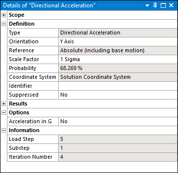
For contour results, the Information category displays the properties described below. These properties are calculated after the associated result is evaluated and they refer to results contained in the results (file.rst) file. The following table describes property values and their result.
Example Details Pane Properties
Property Output Descriptions
Load Step Substep Iteration Number Result Description 3 1 2 1 Sigma Displacement solution. 4 1 3 1 Sigma Velocity solution (if the Calculate Velocity property in Output Controls is set to ). 5 1 4 1 Sigma Acceleration solution (if the Calculate Acceleration property in Output Controls is set to ). See the Review the Results topic in the Performing a Random Vibration (PSD) Analysis section in the Mechanical APDL Structural Analysis Guide for additional information.
The displacement results are relative to the base of the structure (the fixed supports).
The velocity and acceleration results include base motion effects (absolute).
Since the directional results from the solver are statistical in nature they cannot be combined in the usual way. For example the X, Y, and Z displacements cannot be combined to get the magnitude of the total displacement. The same holds true for other derived quantities such as principal stresses.
For directional acceleration results, set the Acceleration in G property to to display the result using the acceleration unit G.
By default the 1 σ results are displayed. You can apply a scale factor to review any multiples of σ such as 2 σ or 3 σ. The Details view as well as the legend for contour results also reflects the percentage (using Gaussian distribution) of time the response is expected to be below the displayed values.
Meaningful equivalent stress is computed using a special algorithm by Segalman-Fulcher. Note that the probability distribution for this equivalent stress is neither Gaussian nor is the mean value zero. However, the "3 σ" rule (multiplying the RMS value by 3) yields a conservative estimate on the upper bound of the equivalent stress.
The Fatigue Tool enables you to perform a Spectral Fatigue analysis using the 1, 2, 3 σ stresses.
For a User Defined result, if you want to request equivalent stress, you must specify SPSD for the Expression property (not SEQV). The SPSD Type uses the Segalman-Fulcher algorithm. SEQV uses a standard method to calculate equivalent stress, and in this instance, is incorrect for the desired 1 Sigma calculation.
To ensure you properly select the SPSD expression, display results in the Solution Worksheet and generate your result from the list of solution quantities. See the User Defined Results for the Mechanical APDL Solver section for additional information.
Force Reaction and Moment Reaction probes can be scoped to a Remote Displacement, Fixed Support, or Displacement boundary conditions to view Reactions Results.
Note:
When you scope a Moment Reaction probe to a Fixed Support or a Displacement, the Summation property must be set to .
The results of Force Reaction and Moment Reaction probes scoped to a Fixed Support or Displacement are calculated using the FSUM Mechanical APDL solver command. This command reports the vector sum of the elemental nodal forces in the global coordinate system. See the FSUM command in the Mechanical APDL Command Reference for more information.
The use of nodal averaging may not be appropriate in a random vibration analysis because the result values are not actual values but standard deviations. Moreover, the element coordinate system for the shell elements in a surface body may not all be aligned consistently when using the Default Coordinate System. Consider using unaveraged results for postprocessing instead.
File Management
When solving a Random Vibration analysis in an "In Process" solve mode, the pre-requisite files from the upstream Modal system are referenced by specifying the full path of their location (refer to RESUME and MODDIR commands) instead of making copies in order to improve solution time and disk usage. See the Solve Modes and Recommended Usage section of the Help for more information about the different solve modes.
When you are solving in the "Out of Process" mode or when the property is set to , the application copies the pre-requisite files from the Modal analysis to the Random Vibration Solver Files Directory. This may increase the required solution time for large models.
Using Command Objects within a Random Vibration Analysis
In an effort to minimize disk space usage, only the results from the Random Vibration analysis are kept in the result file. The results from the Modal analysis are removed during the solution.
If your command object contains commands which require this data, set the Keep Modal Results property in the Output Controls to .