


Introduction
This analysis type is ideal for civil structure designs, such as high-rise buildings undergoing loads from wind as well as nuclear power plant designs experiencing seismic loads.
A Response Spectrum analysis has similarities to the Random Vibration Analysis. However, unlike a random vibration analysis, responses from a response spectrum analysis are deterministic maxima. For a given excitation, the maximum response is calculated based upon the input response spectrum and the method used to combine the modal responses. Combination methods include:
Square Root of the Sum of the Squares (SRSS)
Complete Quadratic Combination (CQC)
Rosenblueth Double Sum Combination (ROSE)
Review the Response Spectrum Options Category topic in the Analysis Settings > Options for Analyses section for more information about these methods.
Points to Remember
The response spectrum is calculated based on modal responses. A modal analysis is therefore a prerequisite.
If response strain/stress is of interest, then the modal strain and the modal stress need to be determined in the modal analysis.
The excitation is applied in the form of a response spectrum. The response spectrum can have displacement, velocity, or acceleration units. For each spectrum value, there is one corresponding frequency.
The excitation must be applied at fixed degrees of freedom.
Because a new solve is required for each requested output (displacement, velocity, and acceleration), the content of a Commands (APDL) object is limited to solution (SOLU) commands.
The results from the Mechanical APDL solver are displayed as the model’s contour plot. The results are in terms of the maximum response.
Preparing the Analysis
As needed throughout the analysis, refer to the Steps for Using the Application section for an overview the general analysis workflow.
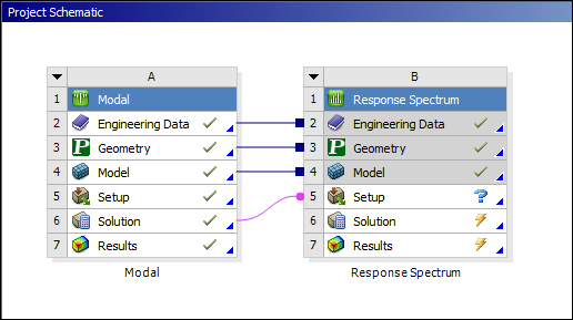
Create Analysis System
Because a response spectrum analysis is based on modal responses, a modal analysis is a required prerequisite. The modal analysis system and the response spectrum analysis system must share resources, geometry, and model data.
Define Engineering Data
Material properties must be defined in a modal analysis. Nonlinear material properties are not allowed.
Define Part Behavior
You can define rigid bodies for this analysis type.
Define Connections
Nonlinear element types are not supported. They will be treated as linear. For example, the contact stiffness is calculated using the initial status without convergence check.
Define Initial Conditions
A specific Modal Environment must be set as an initial condition/environment for response spectrum analysis to be solved.
Establish Analysis Settings
For a Response Spectrum analysis, the basic Analysis Settings include:
- Options for Analyses - Response Spectrum Analyses
Perform the following settings for a Response Spectrum analysis:
Specify the Number of Modes To Use property for the response spectrum calculation. Ansys recommends that you include the modes whose frequencies span 1.5 times the maximum frequency defined in the input response spectrum.
Specify the Spectrum Type to be used for response spectrum calculation as either Single Point or Multiple Points. If the input response spectrum is applied to all fixed degrees of freedom, use Single Point, otherwise use Multiple Points.
Specify the Modes Combination Type to be used for response spectrum calculation. In general, the method is more conservative than the CQC and the ROSE methods.
Note: The Inertia Relief option (under Analysis Settings) for an upstream static structural analysis is not supported in a response spectrum analysis.
- Output Controls
By default, only displacement responses are calculated. To include velocity and/or acceleration responses, set their respective Output Controls to Yes.
- Damping Controls
allow you to specify damping for the structure in the response spectrum analysis. Controls include: Damping Ratio, Stiffness Coefficient (beta damping), and a Mass Coefficient (alpha damping). They can also be applied as Material Damping using the Engineering Data tab. For the CQC mode combination type, non-zero damping is required.
Note: Damping is not applicable to the SRSS combination method. Damping Controls are not available when the Modes Combination Type property is set to .
- Analysis Data Management
These settings enable you to save solution files from the response spectrum analysis. An option to save the Mechanical APDL application database (db file) from the analysis is provided.
Apply Boundary Conditions
Note the following for boundary condition use and processing:
Supported boundary condition types include Fixed Support, Displacement, Remote Displacement and body-to-ground Spring. If one or more fixed supports are defined in the model, the input excitation response can be applied to all fixed supports.
A Remote Displacement cannot coexist with other boundary condition types, such as a Fixed Support or a Displacement, at the same location (scoping) as the excitation. The Remote Displacement will be ignored due to conflict with other boundary conditions.
Note that the All boundary condition types for Single Point Response Spectrum only includes those fixed degree of freedoms defined using Fixed Support, Displacement, Remote Displacement and Body-to-Ground Spring. To apply an RS load to All boundary condition types for Single Point Response Spectrum, at least one allowed boundary condition must be defined.
For a Single Point spectrum type, input excitation spectrums are applied to all boundary condition types defined in the model. For Multiple Points however, each input excitation spectrum is associated to only one boundary condition type.
Three types of input excitation spectrum are supported: displacement input excitation (RS Displacement), velocity input excitation (RS Velocity) and acceleration input excitation (RS Acceleration). See RS Base Excitation for further details.
The input excitation spectrum direction is defined in the global coordinate system for Single Point spectrum analysis. For Multiple Points spectrum analysis, however, the input excitation is defined in the nodal coordinate systems (if any) attached to the constrained nodes.
More than one input excitation, with any different combination of spectrum types, is allowed for the response spectrum analysis.
Specify option to include or not include contribution of high frequency modes in the total response calculation by setting Missing Mass Effect to Yes or No. The option for including the modes is normally required for nuclear power plant design.
Specify option to include or not include rigid responses to the total response calculation by setting Rigid Response Effect to Yes or No. The rigid responses normally occur in the frequency range that is lower than that of missing mass responses, but is higher than that of periodic responses.
Missing Mass Effect is only applicable to RS Acceleration excitation. See the RS Base Excitation section of the Help for more information.
For a Single Point spectrum type, the entire table of input excitation spectrum can be scaled using the Scale Factor setting. The factor must be greater than 0.0. The default is 1.0.
Perform Solution
Ansys recommends that you review the Solution Information page for any warnings or errors that might occur during the solution. You may receive some warning messages and still be able to solve the analysis.
Note: When using a Response Spectrum system from a previous version of the application, it is possible you could encounter incompatibility of for the modal system file(s) file.mode, file.full, and/or file.esav. This incompatibility can cause the Response Spectrum system’s solution to fail. In the event you experience this issue, use the feature and resolve the modal system.
Refer to the Obtain the Spectrum Solution section of the MAPDL Structural Analysis Guide for more information.
Review Results
Note the following for result use and processing:
To view strain/stress results, a selection must be made in Output Controls of the Modal analysis. By default, only Deformation drop-down menu results are available.
Applicable Deformation results are Total, Directional (X/Y/Z), Directional Velocity and Directional Acceleration. If strain/stress are requested, applicable results are normal strain and stress, shear strain and stress, and equivalent stress.
Equivalent stress is a derived stress calculated using component stresses.
Results are displayed as a contour plot on the model.
For contour results, the Information category includes the following properties. These properties are calculated after the associated result is evaluated and they refer to results contained in the results (file.rst) file.
Example Details Properties
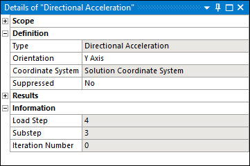
Property Output Descriptions
Load Step Substep Result Description 4 1 Displacement solution. 4 2 Velocity solution (if the Calculate Velocity property in Output Controls is set to ). 4 3 Acceleration solution (if the Calculate Acceleration property in Output Controls is set to ). Note: The value of the Iteration Number property varies based on analysis specifications. It is application defined, is information-based only, and has no impact on results.
You can also see the Review the Results topic in the Performing a Random Vibration (PSD) Analysis section in the Mechanical APDL Structural Analysis Guide for additional information.
If you set the Store Modal Result property of the Output Controls to in the upstream Modal analysis, the application creates additional auxiliary files in addition to standard files. The application automatically creates the Displacement.mcom file. And, if you set the Calculate Velocity and Calculate Acceleration properties (also Output Controls) of the downstream spectrum analysis to , then the application also creates the files Velocity.mcom and/or Acceleration.mcom. These files contain combination instructions as well as mode coefficients.
Note: This configuration increases the computation time of spectrum analysis.
Force Reaction and Moment Reaction probes can be scoped to a Remote Displacement, Fixed Support, or Displacement boundary conditions to view Reactions Results.
Note:When you scope a Moment Reaction probe to a Fixed Support or a Displacement, the Summation property must be set to .
The results of Force Reaction and Moment Reaction probes scoped to a Fixed Support or Displacement are calculated using the FSUM Mechanical APDL solver command. This command reports the vector sum of the elemental nodal forces in the global coordinate system. See the FSUM command in the Mechanical APDL Command Reference for more information.
When the property is set to , the Deformation results that include the data from property in their result calculation are the Directional (Deformation/Displacement) and Directional Acceleration results. Note that the application supports the Directional Velocity result; however, it does not incorporate Missing Mass Effect conditions for its calculation.
The Directional (Deformation/Displacement) result is a relative result whereas Directional Velocity and Directional Acceleration are absolute results.
A Directional Acceleration result at or near fixed supports scoped to an RS Acceleration are correctly calculated by setting the Missing Mass Effect property and the Rigid Response Effect property to . Corresponding properties display and require definition when these two properties are included.
File Management
When solving a Response Spectrum analysis with the "In Process" solve mode, the pre-requisite files from the upstream Modal system are referenced by specifying the full path of their location (refer to RESUME and MODDIR commands) instead of making copies in order to improve solution time and disk usage. See the Solve Modes and Recommended Usage section of the Help for more information about the different solve modes.
When you are solving in the "Out of Process" mode, the application copies the pre-requisite files from the Modal analysis to the Response Spectrum Solver Files Directory. This may increase the required solution time for large models.
For additional technical information, refer to the Spectrum Analysis section of the Mechanical APDL Structural Analysis Guide as well as the MMASS command and the RIGRESP command in the Mechanical APDL Command Reference.