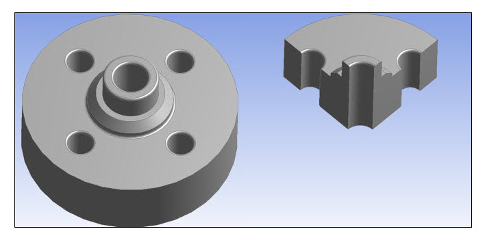
The Symmetry object is a Model-level object in the tree hierarchy. You can insert this object by selecting the Symmetry option on the Model Context Tab.
This feature enables you to use the inherent geometric symmetry of a body to model only a portion of the body for simulation. Using symmetry provides the benefits of faster simulation times and less use of system resources. For example, the model below can be simplified by modeling only ¼ of the geometry by taking advantage of two symmetry planes.

Introduction
Making use of the Symmetry feature requires an understanding of the geometry symmetry and the symmetry of loading and boundary conditions. If geometric symmetry exists, and the loading and boundary conditions are suitable, then the model can be simplified to just the symmetry sector of the model.
DesignModeler can be used to simplify a full model into a symmetric model. This is done by identifying symmetry planes in the body. DesignModeler will then slice the full model and retain only the symmetry portion of the model. (See Symmetry in the DesignModeler help). When the Mechanical application attaches to a symmetry model from DesignModeler, a Symmetry folder is placed in the tree and each Symmetry Plane from DesignModeler is given a Symmetry Region object in the tree. In addition, Named Selection objects are created for each symmetry edge or face. (See Symmetry Workflow in DesignModeler.)
Once you have inserted a Symmetry object into the tree, the following options are available:


