


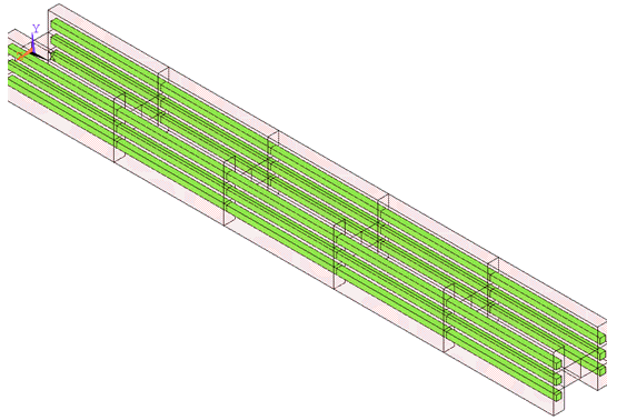
The reinforcing workflow uses structural/thermal reinforcing
elements (REINFnnn) to model embedded members (reinforcing),
which may appear in the form of slender discrete fibers, clusters of fibers with uniform
orientation and spacing, or thin homogeneous membranes.
Reinforcing sections (SECTYPE,,REINF) define the location and orientation of the reinforcing (SECDATA). The sections are referenced by REINF263, REINF264 and REINF265 elements, or MESH200 elements when used to temporarily define reinforcing locations.
The following topics related to the reinforcing workflow are available:
The cross-section area of reinforcing fibers is small compared to the length of the fibers. For a structural analysis, the torsional stiffness is ignored in reinforcing elements. Mechanical APDL considers axial stiffness and can activate transverse shear bending and torsional stiffness in some cases for REINF264 and REINF265 elements. For a thermal analysis, the temperature gradient in the thickness or cross-section direction is ignored.
Mechanical APDL assumes a secure mechanical bond between the reinforcing fibers and the base element. The relative movement between these two components is not permitted; therefore, the motion of reinforcing fibers is determined solely by the motion of the base element. A similar assumption applies in a thermal analysis, where the TEMP field is continuous across the reinforcing fiber and the base element. Based on this simplification, Mechanical APDL adopts the same nodes and connectivity for a reinforcing element and its base element.
Mechanical APDL provides discrete and smeared reinforcing modeling options.
Use the discrete option (SECTYPE,
SECID,REINF,DISC) for modeling reinforcing fibers with nonuniform materials, cross-section areas, or arbitrary orientations. Mechanical APDL models each fiber separately as a spar having only uniaxial stiffness (default) or conductivity, as shown:When solid base elements are used, the elements can also account for bending and torsional stiffness with either square (SECCONTROL,,,1) or circular (SECCONTROL,,,2) cross sections.
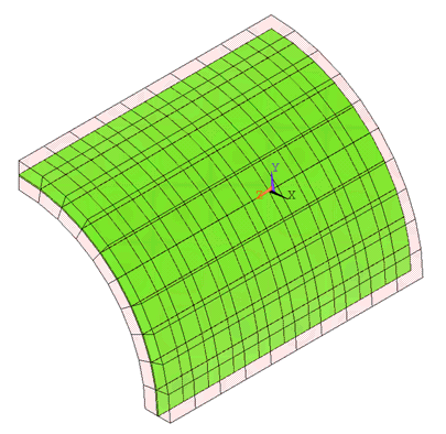
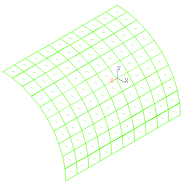
Use the smeared option (SECTYPE,
SECID,REINF,SMEAR) for modeling reinforcing fibers that appear in layered form. Mechanical APDL treats one layer of fibers with identical material, orientation, and cross-section area as a homogeneous membrane having unidirectional stiffness or conductivity, as shown:


For more information about the reinforcing options, see elements REINF263, REINF264, REINF265. Also see REINF263 - 2D Smeared Reinforcing, REINF264 - 3D Discrete Reinforcing, and REINF265 - 3D Smeared Reinforcing in the Mechanical APDL Theory Reference.
Creating reinforcing elements is a two-part process:
Define the reinforcing material, geometry (such as fiber location, cross-section area, and fiber spacing), and fiber orientation.
Two methods are available for defining reinforcing:
Generate the reinforcing elements to embed in other structural or thermal (base) elements.
The mesh-independent method offers much flexibility when the base elements are arbitrary and have no distinct patterns for the reinforcing to attach.
The reinforcing location is represented via a mesh with
MESH200 meshing-facet elements. Other model
information, including reinforcing material, cross-section area, spacing, and
orientation, can be provided via by a reinforcing element
(REINFnnn) section (SECDATA)
or MESH200 element data.
MESH200 elements can be combined with base elements and reinforcing sections in various ways:
Table 14.1: MESH200 Element Options
| Reinforcing Type | MESH200 Options | Compatible Base Elements |
|---|---|---|
| Smeared 2D |
2D lines with 2 or 3 nodes KEYOPT(1) = 0, 1 |
Structural Reinforcing: |
| Smeared 3D |
3D surface with 3-node triangle or 4-node quadrilateral KEYOPT(1) = 4, 5, 6, 7 |
Structural Reinforcing: SOLID185, SOLID186, SOLID187, SOLID285, SOLSH190 Thermal Reinforcing: |
| Discrete 3D |
3D lines with 2 or 3 nodes KEYOPT(1) = 2, 3 |
Structural Reinforcing: SOLID185, SOLID186, SOLID187, SOLID285, SOLSH190 Thermal Reinforcing: |
Using the Mesh-Independent Method:
Create the base elements.
Create MESH200 elements with appropriate reinforcing (REINF
nnn) sections.An initial state can be applied to the MESH200 elements (INISTATE). Only node-based initial state is supported for reinforcing elements generated via the mesh-independent method.
For a thermal analysis, heat generation in fibers can be applied to the MESH200 elements (BFE or BF, for element or nodal body-force loading, respectively).
Select the base elements and the MESH200 elements.
Optional step: If required, optimize the base elements according to the MESH200 elements. For more details about the requirements and limitations, refer the MSHOPTIM command.
Generate the reinforcing elements (EREINF).
For a thermal analysis, heat-generation loads applied to the MESH200 elements are mapped to the newly generated reinforcing elements automatically. (To verify, issue BFELIST or BFLIST, depending on whether you applied element or nodal body-force loading to the MESH200 elements.)
Inspect and verify the newly generated reinforcing elements. (For more information, see Selecting and Displaying Groups of Reinforcing Members.)
As shown in the following example input listings, you can manually adjust the translucency of the base elements to show the reinforcing elements. Additional automatic reinforcing display options are available via the GUI ().
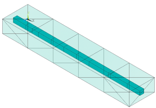
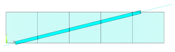
Example 14.1: Discrete-Reinforcing (Mesh-Independent Method)
Following is a typical sequence of commands for defining discrete-reinforcing elements:
/batch,list
/show,sample,grph
/title, Example input data for generating discrete-reinforcing elements
/prep7
!
! define material properties
!
mp,  ex,1,10e6  ! Base Material
mp,  ex,2,30e6  ! Reinforcing Material
mp,prxy,1,.3
mp,prxy,2,.3
mp,dens,1,.00001
mp,dens,2,.00002

! define base elements
et,1,SOLID285
mat,1
block,0,10,0,1,0,2
esize,2
vmesh,1
!
! Define discrete-reinforcing section
!
sectype,2,reinf,discrete
secdata,2,0.1, MESH   ! only MESH pattern is allowed for MESH200
!
! Define MESH200 elements
!
et,2,200,2
mat,2
secnum,2

numstr,line,1001
k,1001,-0.1, 0.5, 1.0
k,2001,10.1, 0.5, 1.0
l,1001,2001

lesize,1001,,,1
lmesh,1001
!
! Create reinforcing elements via EREINF command
!
esel,all
EREINF
!
! Inspect newly created reinforcing elements
!
esel,s,type,,1
! adjust the translucency level of the
! base element to reveal the embedded reinforcing
! elements
/trlcy,elem,0.9
esel,all
/view,1,1,1,1
! Enable the expanded element shapes
/eshape,1
eplot
The input listing generates the following output:
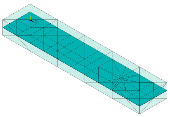
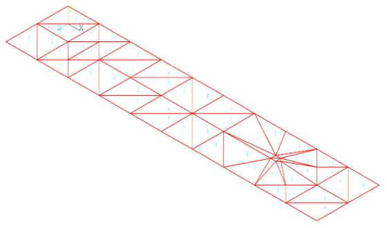
Example 14.2: 2D Smeared Reinforcing (Mesh-Independent Method)
Following is a typical sequence of commands for defining 2D smeared reinforcing elements:
/batch,list
/show,sample,grph
/title, Example input data for generating 2D smeared reinforcing	 elements
/prep7
!
! define material properties
!
mp,  ex,1,10e6  ! Base Material
mp,  ex,2,30e6  ! Reinforcing Material
mp,prxy,1,.3
mp,prxy,2,.3
mp,dens,1,.00001
mp,dens,2,.00002

! define base elements
et,1,183

rect,0,10,0,2
esize,2
amesh,1
!
! Define discrete-reinforcing section
!
sectype,2,reinf,smea
secdata,1,0.1,0.01,,,MESH !Only MESH pattern allowed for MESH200
!
! Define MESH200 elements
!
et,2,200,0

k,10,-0.2,-0.2
k,11,10.5,2.5
l,10,11

type,2
secnum,2
esize,,1
lmesh,5
!
! Create reinforcing elements via EREINF command
!
esel,all
EREINF
!
! Inspect newly created reinforcing elements
!
esel,s,type,,1
! adjust the translucency level of the
! base element to reveal the embedded reinforcing
! elements
/trlcy,elem,0.9
esel,all
! Enable the expanded element shapes
/eshape,0.05
eplot
fini
The input listing generates the following output:
A single new reinforcing section is created and applied to all newly created reinforcing elements. You can examine the properties of the new reinforcing section (SLIST). The program sets the section ID number of the new section to the highest section ID number in the model. When defining subsequent sections, avoid accidentally overwriting of the new reinforcing section.
When reinforcing is embedded in the common face (or edge) of two or more neighboring base elements, the EREINF command suppresses duplicate reinforcing-to-base intersections. If the base mesh is non-conforming (that is, element faces/edges are partially overlapping), the EREINF command may suppress any 3D smeared surface intersections that partially overlap with other intersections.
Example 14.3: 3D Smeared Reinforcing (Mesh-Independent Method)
Following is a typical sequence of commands for defining 3D smeared reinforcing elements:
/batch,list
/show,sample,grph
/title, Example input data for generating 3D smeared reinforcing elements
/prep7
!
! Define material properties
!
mp,  ex,1,10e6  ! Base Material
mp,  ex,2,30e6  ! Reinforcing Material
mp,prxy,1,.3
mp,prxy,2,.3
mp,dens,1,.00001
mp,dens,2,.00002
!
! Define base elements
!
et,1,SOLID285
block,0.0,10.0,0.0,1.0,0.0,2.0
mat,1
esize, 2.0
vmesh, 1
!
! Define smeared reinforcing section
!
sect,2,REINF,SMEAR
secd,2,0.1,0.01,,45.0,MESH
!
! Define MESH200 elements
!
et,2,200,6
type,2
secnum,2
mat,2
aoffst,3,-0.5
ASEL,,,,7
esize,1,
local,11,
esys,11
AMESH,all
!
! Create reinforcing element via EREINF
!
esel,all
csys,0
EREINF
!
! Inspect newly created reinforcing elements
!
esel,s,type,,1
! adjust the translucency level of the
! base element to reveal the embedded reinforcing
! elements
/trlcy,elem,0.9
esel,all
/view,1,1,1,1
eplot
!
! Verify the reinforcing fiber orientation
!
! Switch to the vector plot
/dev,vect,1
! Select only reinforcing elements (optional)
esel,s,type,,3
/psymb,layr,-1
eplot
finish
The input listing generates the following output:
All essential reinforcing data are defined via reinforcing element
(REINFnnn) sections. The reinforcing location is
given directly with respect to the base element connectivity. The standard
method is recommended only when the reinforcing location conforms to the base
elements (such as beams, pipes, and layered elements).
Using the Standard Method:
Create the base elements.
Build the reinforcing sections, with locations defined with respect to base elements via standard location patterns.
Select the base elements to reinforce.
Generate the reinforcing elements (EREINF).
For a thermal analysis, you can simulate heat generation in fibers by applying element body-force loading (BFE) to the newly generated REINF264 or REINF265 elements. (Do not apply nodal body-force loading (BF) to the reinforcing elements.)
Inspect and verify the newly created reinforcing elements.
As shown in the following example input listings, you can manually adjust the translucency of the base elements to show the reinforcing elements. Additional automatic reinforcing display options are available via the GUI ().
Example 14.4: Discrete-Reinforcing (Standard Method)
Following is a typical sequence of commands for defining discrete-reinforcing elements via the standard method:
/batch,list
/show, sample,grph
/title, Example input data for generating discrete-reinforcing elements
/prep7
!
! Define material properties
!
mp,  ex,1,10e6  ! Base Material
mp,  ex,2,30e6  ! Reinforcing Material
mp,prxy,1,.3
mp,prxy,2,.3
mp,dens,1,.00001
mp,dens,2,.00002
!
! Define base geometry
!
k,1, 0.,0.
k,2,10.,0.
l,1,2
!
! Define base elements
!
et,1,BEAM188
mat,1
sect,1,BEAM,I
secd,1.,1.,1.,0.2,0.2,0.3
esize, 2.0
lmesh, 1
!
! Define discrete-reinforcing section
!
sect,2,REINF,DISC
secd,2,0.01,BEAM,-0.25,0.1
secd,2,0.01,BEAM, 0 .0,0.1
secd,2,0.01,BEAM, 0.25,0.1
secd,2,0.01,BEAM,-0.25,0.9
secd,2,0.01,BEAM, 0 .0,0.9
secd,2,0.01,BEAM, 0.25,0.9
!
! Create reinforcing element via EREINF
!
esel,all
secn, 2 ! use reinforcing section!
EREINF
!
! Inspect newly created reinforcing elements
!
esel,s,type,,1
! adjust the translucency level of the
! base element to reveal the embedded reinforcing
! elements
/trlcy,elem,0.9
esel,all
/view,1,1,1,1
! Enable the expanded element shapes
/eshape,1
eplot
fini
The input listing generates the following output:
Example 14.5: Smeared Reinforcing (Standard Method)
Following is a typical sequence of commands for defining smeared reinforcing elements via the standard method:
/batch,list
/show, sample,grph
/title, Example input data for generating smeared reinforcing elements
/prep7
!
! Define material properties
!
mp,  ex,1,10e6  ! Base Material
mp,  ex,2,30e6  ! Reinforcing Material
mp,prxy,1,.3
mp,prxy,2,.3
mp,dens,1,.00001
mp,dens,2,.00002
!
! Define base geometry
!
CYLIND, 10.,12.,0.,20.,0,90.
!
! Define base elements
!
et,1,SOLID185
mat,1
esize, 2.0
vmesh, 1
!
! Define smeared reinforcing section
!
sect,1,REINF,SMEAR
secd,2,0.1,1.0,,45.0,ELEF,3,0.5
!
! Create reinforcing element via EREINF
!
esel,all
EREINF
!
! Inspect newly created reinforcing elements
!
esel,s,type,,1
! adjust the translucency level of the
! base element to reveal the embedded reinforcing
! elements
/trlcy,elem,0.9
esel,all
/view,1,1,1,1
! Enable the expanded element shapes
/eshape,1
eplot
!
! Verify the reinforcing fiber orientation
!
! Switch to the vector plot
/dev,vect,1
! Select only reinforcing elements (optional)
esel,s,type,,2
/psymb,layr,-1
eplot
fini
The input listing generates the following output:
A single EREINF command generates reinforcing elements according to your defined reinforcing material, geometry, and fiber orientation. The command determines the reinforcing element type, and creates and stores new reinforcing. (Standard element-definition commands such as ET and E are not used.)
Reinforcing elements ignore any subsequent modifications made to the base elements. ANSYS, Inc. recommends issuing the EREINF command only after you have finalized the base elements. If you delete or modify base elements after generating the reinforcing elements, remove all affected reinforcing elements and reissue the EREINF command to avoid inconsistencies.
The EREINF command operates differently according to the method used to define reinforcing:
14.1.3.3.1. Using EREINF with the Mesh-Independent Method
The EREINF command determines the reinforcing element type according to the base element type, the MESH200 element type, and the reinforcing section associated with the MESH200 elements.
The command rejects MESH200 elements if their locations do not meet the requirements:
Table 14.2: Element Location and EREINF Command Action
| MESH200 Element Location | EREINF Action |
|---|---|
| Fully embedded in a homogeneous solid element | Accept |
| Fully outside of a homogeneous solid element | Reject |
| Partially embedded in a homogeneous solid element | Keep only the portion embedded |
| Non-parallel to a link, beam, or pipe element | Reject |
| Outside of the cross-section of a link, beam, or pipe element | Reject |
| Partially embedded in a link, beam, or pipe element | Keep only the portion embedded |
| Non-parallel to the shell surface or layers in a layered solid element | Reject |
| Outside of the shell section or the layered solid element | Reject |
| Partially embedded in a shell or layered solid element | Keep only the portion embedded |
14.1.3.3.2. Using EREINF with the Standard Method
The EREINF command determines the reinforcing element type according to the base element type and the current reinforcing section. The command generates no new reinforcing elements if the current section is not a valid reinforcing section or if the section is incompatible with the base elements.
To define a section ID to associate with subsequently-defined reinforcing elements, issue the SECNUM command.
Reinforcing locations are given with respect to the base element. Unexpected reinforcing placement may result from incorrectly oriented base elements. You can adjust the desired base element orientation (EORIENT or VEORIENT). In some cases, you may need to create different reinforcing sections for different base elements with inconsistent orientations.
If smeared reinforcing elements REINF263 and REINF265 are generated via the mesh-independent method, the coordinate system of a reinforcing layer matches that of the MESH200 element.
If smeared reinforcing elements are generated via the standard method, the default coordinate
system of a reinforcing layer is determined using the parametric direction of
the layer. The layer coordinate system can be reoriented by defining local
coordinate system KCN and/or orientation angle
THETA:
SECDATA,,,
KCN,THETA
Because the fiber direction is same as the layer x axis, reorientation of the layer coordinate system also reorients the fiber direction.
The default coordinate system of discrete-reinforcing element REINF264 is determined solely by intersection points and cannot be reoriented.
For the mesh-independent method, refer to MESH200. The following topics describe the coordinate system with the standard method:
14.1.3.4.1. Coordinate System of 3D Smeared-Reinforcing Layer (REINF265, Standard Method)
The following figure shows the default coordinate system (x0, y0, z0) for one reinforcing layer of a linear 3D smeared-reinforcing element:
Figure 14.10: Coordinate System of a Reinforcing Layer
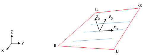
X, Y, Z: Global coordinate system x0, y0, z0: Default layer coordinate system
The x axis (x0) is defined by the first parametric direction S1 at the center of the layer. The normal axis (z0) is perpendicular to the layer. The x axis represents the direction of reinforcing fibers in the layer.
Three options are available for reorienting the layer coordinate system:
Define a local coordinate system
KCN(SECDATA,,,KCN).Result: The program projects the local coordinate system on the layer and determines the layer x axis (x0).
Define an orientation angle
THETA(SECDATA,,,,THETA).Result: The program determines the layer x axis (x0) by the first parametric direction S1, then rotates the x axis by the orientation angle (
THETA).Define both a local coordinate system
KCNand an orientation angleTHETA(SECDATA,,,KCN,THETA).Result: The program projects the local coordinate system on the layer and determines the layer x axis (x0), then rotates the local coordinate system further by the orientation angle (
THETA).
Figure 14.11: Reoriented Coordinate System of a 3D Smeared Reinforcing Layer
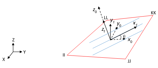
X, Y, Z: Global coordinate system x0, y0, z0: Default layer coordinate system xf, yf, zf: Actual layer coordinate system, where the layer x axis (xf) represents the fiber direction θ: Orientation angle determined by KCNand/orTHETA
14.1.3.4.2. Coordinate System of 2D Smeared-Reinforcing Layer (REINF263, Standard Method)
The following figure shows the default coordinate system of a linear 2D smeared-reinforcing layer:
Figure 14.12: Coordinate System of 2D Smeared-Reinforcing Layer
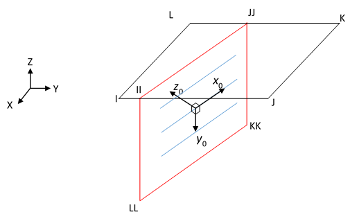
X, Y, Z: Global coordinate system x0, y0, z0: Default layer coordinate system
The x axis of the layer coordinate system defaults to the first parametric direction S1 of the segment defined by intersection points II and JJ. Because the 2D smeared-reinforcing element is modeled as a line segment, the reinforcing layer is shown as an extended plane with respect to the segment from II to JJ. The layer y axis (y0) is defined as the -Z axis. The normal axis (z0) is determined by the product of two horizontal axes x0 and y0.
The options to reorient the coordinate system of a 2D smeared reinforcing layer are similar to those for the 3D smeared-reinforcing layer; however, the reorientation calculation is performed on the extended plane.
Figure 14.13: Reoriented Coordinate System of a 2D Smeared-Reinforcing Layer
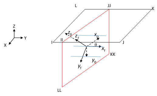
X, Y, Z: Global coordinate system x0, y0, z0: Default layer coordinate system xf, yf, zf: Actual layer coordinate system θ: Orientation angle determined by KCNand/orTHETA
14.1.3.4.3. Coordinate System of a 3D Discrete-Reinforcing Element (REINF264, Standard Method)
The default coordinate system of a 3D discrete-reinforcing element is determined by the intersection points II and JJ (or II, JJ, and KK for a high-order element). The coordinate system cannot be reoriented.
Figure 14.14: Coordinate System of 3D Discrete-Reinforcing Element
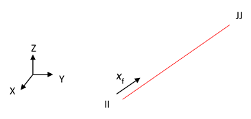
X, Y, Z: Global coordinate system xf: Local x axis representing the fiber direction
The mesh-independent method for defining reinforcing is especially useful for generating the reinforcing elements in complex geometry.
Because reviewing and verifying the many generated reinforcing elements and members (individual reinforcings) in a geometrically complex model can be difficult, Mechanical APDL provides a tool (EMSEL) for selecting one or more reinforcing members based on a predefined global identifier (EGID).
The general procedure for defining and selecting a group of reinforcing members is:
Create the base elements.
Define a global ID (EGID) for the subsequent set of MESH200 elements.
Create the MESH200 elements with appropriate reinforcing (REINF
nnn) sections.To define multiple sets, repeat steps 2 and 3 as needed.
Select the base elements and the MESH200 elements.
Inspect and verify the newly generated reinforcings. Issue the EMSEL command to select and display a group of reinforcing members according to specified global IDs (EMSEL).
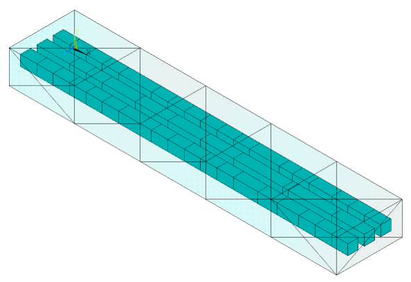
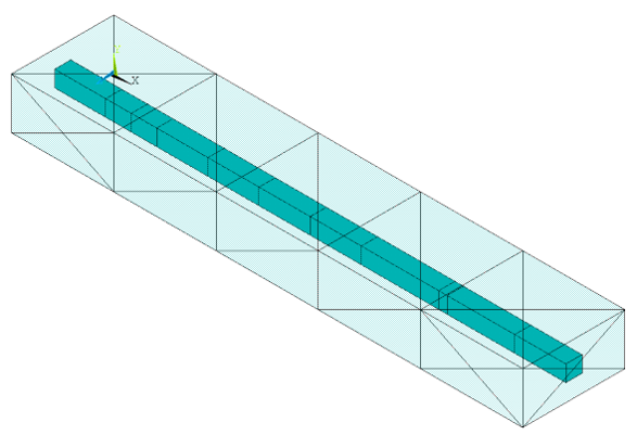
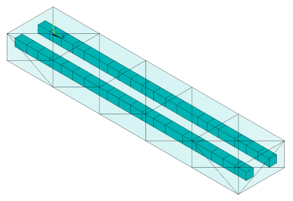
Example 14.6: Defining Sets of Reinforcing Elements
/prep7
!
! define material properties
!
mp,  ex,1,10e6  ! Base Material
mp,  ex,2,30e6  ! Reinforcing Material
mp,prxy,1,.3
mp,prxy,2,.3
mp,dens,1,.00001
mp,dens,2,.00002

! define base elements
et,1,SOLID285
mat,1
block,0,10,0,1,0,2
esize,2
vmesh,1
!
! Define discrete-reinforcing section
!
sectype,2,reinf,discrete
secdata,1,0.05, MESH ! only MESH pattern is allowed for MESH200
!
! Define MESH200 elements
!
et,2,200,2
mat,2
secnum,2

numstr,line,1001

k,1001,-0.1, 0.5, 0.5
k,1002,10.1, 0.5, 0.5
k,2001,-0.1, 0.5, 1.0
k,2002,10.1, 0.5, 1.0
k,3001,-0.1, 0.5, 1.5
k,3002,10.1, 0.5, 1.5

l,1001,1002
l,2001,2002
l,3001,3002

lsel,,line,,1001,1003
lesize,all,,,1

allsel

! Generate MESH200 elements with global ID = 1
egid,1
lmesh,1001

! Generate MESH200 elements with global ID = 2
egid,2
lmesh,1002

! Generate MESH200 elements with global ID = 3
egid,3
lmesh,1003
!
! Create reinforcing elements via EREINF
!
esel,all
EREINF
!
! Inspect newly created reinforcing elements
!
esel,s,type,,1
! adjust the translucency level of the
! base element to reveal the embedded reinforcing
! elements
/trlcy,elem,0.9

esel,all
esel,u,ename,,200

/view,1,1,1,1

! Enable the expanded element shapes
/eshape,1

! Display all elements/members
eplot
The example input listing generates the following output (with translucent base elements):
Base-element characteristics may change after the reinforcing
(REINFnnn) elements have been generated.
To account for base-element changes in the reinforcing elements efficiently, select the reinforcing elements that need to be updated and issue EREINF.
The update capability is especially useful if the base-element degree-of-freedom set changes and you want to reflect that change in the reinforcing elements.
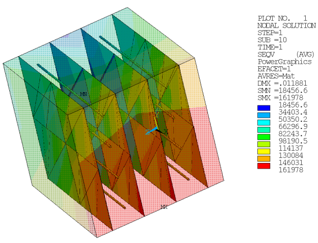
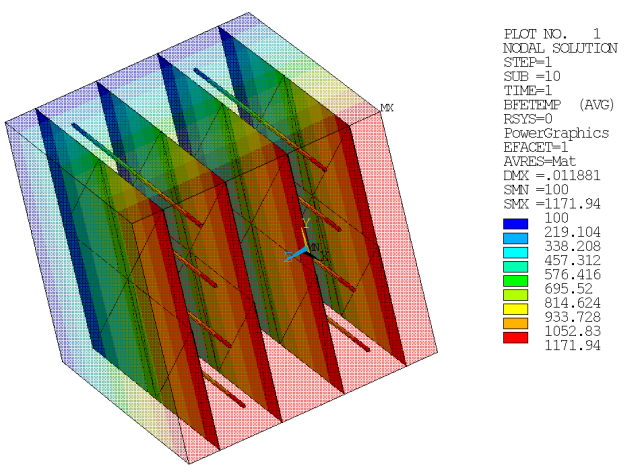
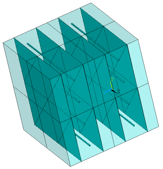
Example 14.9: Updating Reinforcing Elements in a Thermal Stress Analysis
In this example, EREINF is issued three times, twice to generate reinforcing elements for the thermal analysis, and the third time to update the reinforcing elements for a subsequent structural analysis:
/batch,list
! Thermal Analysis
/PREP7
n        = 2     ! how much the unit cube should be split => n^3 cube elements
heat_gen = 1000  ! Heat generation applied to MESH200 elements

! Thermal material properties of base and reinforcing materials
mp,kxx,1,10
mp,dens,1,2
mp,c,1,3.0
mp,kxx,2,10
mp,dens,2,2
mp,c,2,3.0

! Unit Cube generation
block,0,1,0,1,0,1
et,1,278
esize,(1/n)
vmesh,1
alls

! Mesh-independent reinforcing generation from MESH200

! Smeared reinforcements MESH200
*get,kpt1,kp,0,num,max
*get,are1,area,0,num,max
z=0
*do,i,kpt1+1,kpt1+(8*n),8
  k,i,  0,0,(1/(4*n))+z
  k,i+1,1,0,(1/(4*n))+z
  k,i+2,1,1,(1/(4*n))+z
  k,i+3,0,1,(1/(4*n))+z
  k,i+4,0,0,(3/(4*n))+z
  k,i+5,1,0,(3/(4*n))+z
  k,i+6,1,1,(3/(4*n))+z
  k,i+7,0,1,(3/(4*n))+z
  a,i,i+1,i+2,i+3
  a,i+4,i+5,i+6,i+7
  z=(z+(1/n))
*enddo
alls
*get,are2,area,0,num,max
sect,1,reinf,smear
secd,2,0.15,1,,,mesh
secc,,1,1
et,2,200,6
secn,1
esize,(1/n)
*do,j,are1+1,are2,1
 amesh,j
*enddo
alls

! Discrete reinforcings MESH200
*get,kpt2,kp,0,num,max
*get,lin1,line,0,num,max
y=0
*do,a,1,n
z=0
 *do,i,kpt2+1,kpt2+(4*n),4
   k,i  , 0,(1/(4*n))+y,(1/(2*n))+z
   k,i+1, 1,(1/(4*n))+y,(1/(2*n))+z
   k,i+2, 0,(3/(4*n))+y,(1/(2*n))+z
   k,i+3, 1,(3/(4*n))+y,(1/(2*n))+z
   l,i,i+1
   l,i+2,i+3
   z=(z+(1/n))
 *enddo
kpt2=kpt2+(4*n)
y=(y+(1/n))
*enddo
alls
*get,lin2,line,0,num,max
sect,2,reinf,disc
secd,2,0.1,mesh
secc,,1
et,3,200,2
secn,2
*do,j,lin1+1,lin2,1
 lesize,j,(1/n)
 lmesh,j
*enddo
alls

! Apply heat generation on MESH200
esel,s,ename,,200
bfe,all,hgen,1,heat_gen
alls

! Create reinforcements
esel,s,type,,1  ! Select base elems
esel,a,type,,2  ! Select mesh200 quads
ereinf          ! Create REINF265 elements and transfer Hgen
esel,s,type,,1  ! Select base elems
esel,a,type,,3  ! Select mesh200 lines
ereinf          ! Create REINF264 elements and transfer Hgen
alls

bfelist

fini

/SOLU
!sfgrad,hflux,0,y,0,1000
nsel,s,loc,x,0
d,all,temp,100
nsel,s,loc,x,1
sf,all,hflux,10000
alls
outres,all,all
SAVE
SOLVE
fini

/POST1
set,last
alls
presol,tg
presol,tf
presol,bfe,temp
fini


! Down-stream structural analysis
/PREP7

! Structural material prop of base & reinf mtl
mp,alpx,1,1e-5
mp,ex,1,10e6
mp,prxy,1,.3
mp,alpx,2,1e-5
mp,ex,2,10e6
mp,prxy,2,.3

et,1,185              ! Change base element from thermal to structural
esel,s,ename,,264,265 ! Select only the REINF elements
ereinf                ! Update REINF elements to have structural dofs
slist
elist
etlist

/SOLU
nsel,s,loc,x,0
d,all,all,0
alls
ldread,temp,,,,,,rth
nlgeom,on
nsub,10,100,10
resc,define,all,1
bflist
SAVE
SOLVE
fini

/POST1
prnsol,dof
presol,s
fini
/exit,nosave
The example input generates the following output:
After generating reinforcing elements (EREINF), you can apply an initial state directly on each element (INISTATE).
For cases involving many elements, an easier and more efficient method is available. Using the mesh-independent method for defining reinforcing, you can apply an initial state to the MESH200 meshing-facet element. Mechanical APDL then transfers the initial state to the newly generated reinforcing elements automatically.
Following is the process for applying an initial state to reinforcing elements via the mesh-independent method:
Create the base elements.
Create MESH200 elements with appropriate reinforcing (REINF
nnnelement) sections.Define initial-state data and parameters (INISTATE) at nodes of the MESH200 elements.
Select the base elements and the MESH200 elements.
Generate the reinforcing elements (EREINF).
Examine and verify the newly created reinforcing elements and initial state.
Only node-based initial state is supported for reinforcing elements generated via the mesh-independent method. (For the element-based format, input is ignored.)
Example 14.10: Applying an Initial State to Reinforcing Elements via the Mesh-Independent Method
/batch,list
/title, Example input data for applying initial state to reinforcing elements via mesh-independent method
/prep7
!
! Define material properties
!
mp,ex,1,10e2  ! Base Material
mp,nuxy,1,.3
mp,ex,2,1e10  ! Reinforcing Material
mp,prxy,2,0.2
!
! Define sections
!
sect,1,beam,rect          ! Section for base element
secd,0.1,0.1
sectype,2,reinf,discrete  ! Discrete reinforcing section
secdata,2,0.001,mesh
!
! Define base element
!
et,1,188,,,
secn,1
n,1,
n,2,1.0
e,1,2
!
! Define mesh200 element
!
et,2,200
n, 101, 0.0, -0.025, 0.025
n, 102, 1.0, -0.025, 0.025
n, 103, 0.0,  0.025,-0.025
n, 104, 1.0,  0.025,-0.025
type,2
mat,2
secnum,2
e,101,102
e,103,104
!
! Define node-based initial state on the MESH200 elements
!
INIS,SET,NODE,1
INIS,DEFI,101 , , , ,100.0
INIS,DEFI,102 , , , ,100.0
INIS,DEFI,103 , , , ,100.0
INIS,DEFI,104 , , , ,100.0
!
! Create reinforcing element via EREINF
!
alls
ereinf
!
! Check initial state data of reinforcing element
!
esel,s,ename,,264
inis,list
For more information, see Initial State in the Advanced Analysis Guide.
The REINF263, REINF264, and REINF265 reinforcing elements have plasticity, stress stiffening, creep, large deflection, initial stress, and large strain capabilities. REINF264 and REINF265 also have thermal capability. You can use the reinforcing elements in any type of simulation that their base elements support.
For structural analyses, reinforcing elements allow tension-only (cable) and compression-only (gap) options. You can specify those options via the SECCONTROL command. A nonlinear iterative solution procedure is necessary for simulating the tension-only or compression-only behaviors.
Reinforcing elements always list or display stress and strain, or temperature gradient and thermal heat flux, results in local fiber directions; therefore, the coordinate system specified for displaying the results (RSYS) has no effect. Display of reinforcing results is supported in both PowerGraphics and FullGraphics:
In PowerGraphics mode, a single reinforcing member (individual reinforcing) or a group of members can be displayed at one time. To specify a given member or group of members to display, issue the EMSEL command (also available in PREP7).
In FullGraphics mode, only one reinforcing member can be displayed at one time. To specify the desired member to display in FullGraphics mode, issue the LAYER command.
Issue standard postprocessing commands (PLESOL, PRESOL, etc.) to plot or print the output results of the selected members.
You can perform a failure analysis on the reinforcing elements. For more information, see Specifying Failure Criteria for Composites.