


Defines a set of bodies as a single superelement with the overall inertial and flexibility behavior summarized on a reduced set of degrees of freedom. This allows flexible bodies to participate in Rigid Dynamics solver, by exposing only the master nodes necessary to define applicable joints, springs and other connections in the model. It also enables the synthesis of vibration behavior of more complex structures by assembling Condensed Parts with other parts in Modal, Rigid Dynamics, and Harmonic Response (MSUP), Random Vibration, Response Spectrum, and Motion analyses.
Important: Once you have scoped and generated Condensed Parts, any mesh modifications made to the parts of the model that do not belong to the generated Condensed Parts, do not require you to regenerate the Condensed Parts. That is, Condensed Parts maintain an up-to-date status following mesh changes to other model parts. However, there are mesh update exceptions. If you subsequently apply one or more of the features listed below, your Condensed Parts become obsolete and need to be regenerated.
Mesh Edit
Element Orientation
Mesh Numbering
And, Condensed Parts require regeneration if you make any geometry modifications in the CAD application. This applies even if you have the Smart CAD Update option (SpaceClaim only) of the Advanced Geometry Options in Geometry cell properties of the Project Schematic. See the Geometry Preferences section in the CAD Integration documentation for more information.
 |
Object Properties
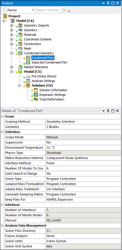
The Details Pane properties for this object include the following.
| Category | Properties/Options/Descriptions |
|---|---|
|
Scope |
Scoping Method: (default) or . Geometry: Visible when the Scoping Method is set to . Displays the type of geometry (Body only) and the number of geometric entities (for example: 1 Body) for your selections. Named Selection: Visible when the Scoping Method is set to . This field provides a drop-down list of available user-defined Named Selections. |
|
Definition |
Scope Mode: Read-only property indicating the scoping mode (). Suppressed: or . Environment Temperature: The default setting is 22°C. Used for the evaluation of temperature-dependent material properties. In addition, this value is used as the material reference temperature for the condensed part bodies. Physics Type: Read-only property indicating the physics type (). Matrix Reduction Method: Read-only property indicating the Component Mode Synthesis (CMS) method. Interface Method: Options include (default) or . Number of Modes to Use: Displays the number of modes to be used for the generation pass solve. Limit Search to Range: Options include or (default). If set to Yes, the Range Minimum, and Range Maximum properties display. Range Minimum: Defines the minimum frequency for the specified CMS modes. Range Maximum: Defines the maximum frequency for the specified CMS modes. Solver Type Lumped Mass Formulation: Options include (default) or , and . Added Mass Treatment: Specifies how the added masses (from Point Mass and Distributed Mass) are treated by the Condensed Part. Options include and (default). Generate Damping Matrix: Options include (default), , and . Selecting or generates stiffness, mass, and damping matrices. When you select , the application generates only stiffness and mass matrices and does not generate damping matrices. Refer to the SEOPT command in the Mechanical APDL Command Reference for more details. Keep Files For: Specifies which files the application generates during the solution. Options include:
|
|
Interfaces |
Number of Interfaces: Read-only display of the number of interface entries detected by the application. Number of Master Nodes: Read-only display of the number of superelement master nodes resulting from interfaces. |
|
Analysis Data Management |
These properties mimic Analysis Settings for Most Analysis Types for Analysis Data Management. See the Analysis Data Management section of the Help for additional information. Solver Files Directory: Read-only property indicating the location of the solution files for this analysis. Future Analysis: Options include , or (default). Solver Units: Options include (default) or . Solver Unit System: Based on the setting of the Solver Units property. It is read-only if is selected, otherwise you can select the system when the property is set to . |
|
Statistics |
Number of Master Nodes: Read-only property available (only) when you generate (generation pass) the Condensed Part object. It displays the number of master nodes generated for the part. The value of this property gets updated only when you execute the operation again. |
Tree Dependencies
Valid Parent Tree Object: Condensed Geometry.
Valid Child Tree Object: Commands.
Insertion Methods
Use any of the following methods after selecting the Condensed Geometry object:
Select the Condensed Part option from the Condensed Geometry Context tab.
Select via the Condensed Geometry object.
Right-click the Condensed Geometry object and select > Condensed Part.
Right-click in the Geometry window and then select > .
Right-click Options
In addition to common right-click options, relevant right-click options for this object include:
>
: Insert a new object.
: Insert a new Specifying Solution Information.
: Insert a new Command Object.
: Perform a generation pass on the selected Condensed Part object(s).
Important:Once you have scoped and generated Condensed Parts, any mesh modifications made to the parts of the model that do not belong to the generated Condensed Parts, do not require you to regenerate the Condensed Parts. That is, Condensed Parts maintain an up-to-date status following mesh changes to other model parts. However, there are a few exceptions. If you have imported your model using external systems, External Model and/or Mechanical Model systems, any geometry modifications to geometries not specified as a Condensed Part, do cause the Condensed Parts to become obsolete and require regeneration. In addition, the use of features such as Mesh Edit, Element Orientation, or Mesh Numbering objects cause up-to-date Condensed Parts to become obsolete and require regeneration.
The generation of Condensed Parts is performed using the Distribute Solution and the Max number of utilized cores options defined in the Advanced Settings of the Solve Process Settings dialog. It is recommended that you use the same number of cores for generating all condensed parts and solving the analysis.
Solution processing using the Remote Solve Manager (RSM) is currently not supported.
: Automatically generate the interfaces for a Condensed Part object.
Note:
Imported loads and connections are not automatically detected as interfaces. You need to add the corresponding master nodes via a Named Selection on the Condensed Part Worksheet.
Loads that can be scoped to bodies, such as Acceleration, are not detected automatically as interfaces if the loads are scoped to condensed part(s).
API Reference
See the Condensed Part section of the ACT API Reference Guide for specific scripting information.
Additional Related Information
See the following sections for more information:
Expansion Settings on the Worksheet: See the Expansion section.