The Behavior option dictates the behavior of the attached geometry. You can specify the Behavior of the scoped geometry for a remote boundary condition in the Details as either , , , or .
Note: The Ansys Explicit Dynamics solver only supports Rigid Behavior.
Deformable: The geometry is free to deform. This is a general purpose option used when applying boundary conditions such as a force or mass through "abstract" entities not explicitly represented as geometry inside Mechanical. This formulation is similar to the Mechanical APDL constraint defined by the RBE3 command.
Rigid: The geometry will not deform (maintains the initial shape). This option is useful when the "abstracted" object significantly stiffens the model at the attachment point. Note that thermal expansion effects cause artificially high stresses because the geometry cannot deform where the load is applied. This formulation is similar to the Mechanical APDL constraint defined by the CERIG command.
Coupled: The geometry has the same DOF solution on its underlying nodes as the remote point location. This is useful when you want a portion of geometry to share the same DOF solution (such as UX) that may or may not be known. For example, to constrain a surface to have the same displacement in the X direction, simply create a remote point, set the formulation to Coupled, and activate the X DOF. Because the DOF is known, you can specify an additional Remote Displacement. This formulation is similar to the Mechanical APDL constraint defined by the CP command.
Beam: This option specifies that the Remote Point is connected to the model using linear massless beam elements (BEAM188). This approach is more direct than using Constraint Equations and can help prevent over-constraint issues that can occur with CE's. The following two user-defined properties are available to define the connection:
Material: Specifies the material properties, except density, that will be used for the beam connections. The application does not include the material properties for the Coefficient of Linear Thermal Expansion by default. As a result, this may develop thermal differential strains when thermal conditions are applied to the model. To address this issue, use Line Bodies with the necessary user-defined material properties instead of a Remote Point.
Radius: Defines the cross section dimension of the circular beam (CSOLID) and is sent to the Mechanical APDL solver via the SECDATA command.
The Beam formulation can be useful when working with shells. For example, when you are trying to model Spot Welds between two sheet bodies with holes.
Important: When you apply a thermal load to your model, thermal differential strains can develop when using the option. This is because the thermal loading does not become properly associated to the automatically generated beam elements created to make the connection.
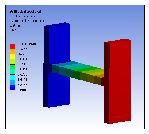
You must determine which Behavior best represents the actual loading. Note that this option has no effect if the boundary condition is scoped to a rigid body in which case a behavior is always used. Presented below are examples of the Total Deformation resulting from the same Remote Displacement, first using a formulation, then using a formulation, and finally the formulation.
Rigid Behavior
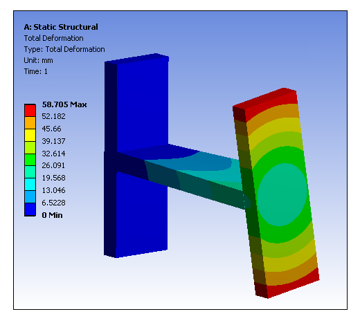
Deformable Behavior
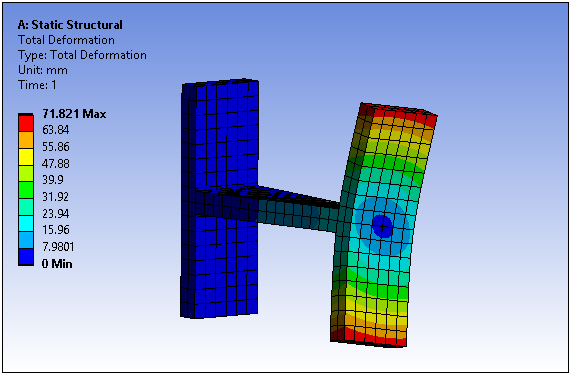
Coupled Behavior