


Introduction
The Coupled Field analyses in Mechanical enable you to simulate interaction between multiple physics types. The availability of analysis settings, boundary conditions, results, etc. is based on the specified physics as well as the analysis type you select. For example, if you specify a Coupled Field Static analysis, all common features are available for structural physics, such as Force, Deformation, etc. Supported physics configurations include:
| Coupled Field Harmonic | Coupled Field Modal | Coupled Field Static | Coupled Field Transient | |
|---|---|---|---|---|
| Structural | ✓ | ✓ | ✓ | ✓ |
| Acoustics | ✓ | ✓ | ✓ | ✓ |
| Electric | ✓[a] | ✓[a] | ✓[b] | ✓[b] |
| Thermal | ✓ | ✓ |
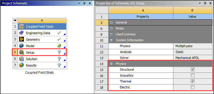
You can view the physics specified for your Coupled Field analysis from the properties of the Setup cell in Workbench.
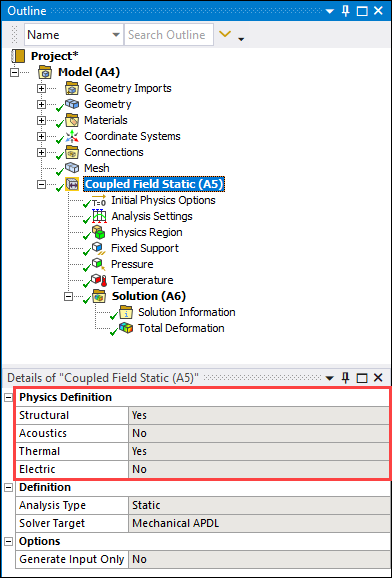
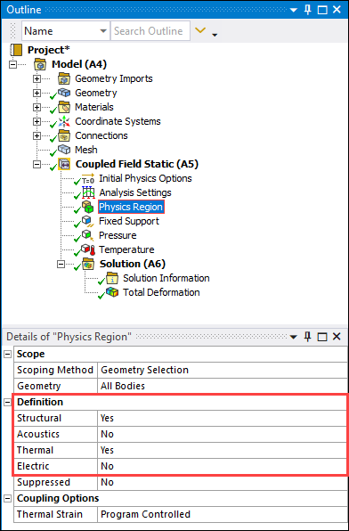
And, in Mechanical, you can view the selected physics from the Environment object, and you can view and change the physics definition using the Physics Region object.
|
|
|
Coupling
The following table shows the interaction between the types of physics available in the application and the analysis types. You specify the interaction between the physics types and the analyses using either the 1) Physics Region, such as Thermal Strain, or through 2) coupling conditions, such as Plastic heating, or 3) the application always includes Piezoelectric coupling via Structural-Electric charge interaction.
|
Physics |
Coupled Field Harmonic |
Coupled Field Modal |
Coupled Field Static |
Coupled Field Transient |
|---|---|---|---|---|
|
Structural Thermal |
Not Supported |
Thermal strain Thermoplasticity Thermoviscoelasticity |
Thermal strain Thermoelastic Damping Thermoplasticity Thermoviscoelasticity | |
|
Electrostatic Structural |
Electrostatic Force[a] |
Electrostatic Force[a] |
Electrostatic Force |
Electrostatic Force |
|
Structural-Acoustics |
Fluid Solid Interface |
Fluid Solid Interface |
Fluid Solid Interface |
Fluid Solid Interface |
|
Structural Electric (Charge) |
Piezoelectric |
Piezoelectric |
Piezoelectric |
Piezoelectric |
|
Thermal Electric (Conduction) |
Joule Heating Seebeck Peltier |
Joule Heating Seebeck Peltier |
[a] Requires prestress Coupled Field Static.
Important: The property of the Geometry object is, by default, set to . This setting allows the application to choose the best Mechanical APDL element options (KEYOPTS). For example, if your coupled field analysis includes nonlinearities, the application could automatically (and without your knowledge):
Change the structural-thermal coupling from to .
Specify that all coupling types use a uniform reduced integration scheme instead of Full Integration (as defined by the Brick Integration Scheme property of Part/Body objects).
As a result, to make sure that the application does not automatically change the element options, use the setting for the property.
See the Automatic Selection of Element Technologies and Formulations section of the Mechanical APDL Element Reference for more information.
Note:
The Physics Region supports the activation of more than two physics types and therefore, coupling. In this case, there is a cumulative effect for each individual physics interaction with the other supported physics.
If a body has more than two physics associated with its scoping, the interaction of the physics types is a combination of two different physics interactions.
You can set the Thermal Strain property, of Physics Region object, to (Matrix) coupling or (Load Vector) coupling. Review the Coupled Effects section of the Coupling documentation in the Mechanical APDL Theory Reference for more background information.
You can specify Thermoplasticity and Thermoviscoelasticity using the Plastic Heating and Viscoelastic Heating coupling conditions. Review the Thermoplasticity and Thermoviscoelasticity sections of the Coupling documentation in the Mechanical APDL Theory Reference for more background information.
Joule Heating is considered as a load vector. Review the Thermoelectrics section of the Coupling documentation in the Mechanical APDL Theory Reference for more background information.
For Piezoelectric coupling, the Piezoelectric matrix must be defined in the Engineering Data Workspace. You may want to review the Piezoelectrics section of the Coupling documentation in the Mechanical APDL Theory Reference for more background information.
Currently, linear elements generated by the application use element SOLID226 (a high-order element) with the mid-side nodes dropped, except for structural-thermal coupling and piezoelectric coupling. For structural-thermal coupling and piezoelectric coupling, the application uses element SOLID225.
Recommendation: If your coupled field analysis includes an edge that you can more accurately measure in micrometers than meters, Ansys recommends that you use a unit system that supports this length, specifically the µMKS unit system.
Coupled Field Simulations
The following sections discuss the steps and requirements to perform, processing limitations of, and industry-based applications for, coupled field simulations.
- 5.2.1. Coupled Field Harmonic Analysis
- 5.2.2. Prestressed Coupled Field Harmonic Analysis
- 5.2.3. Coupled Field Modal Analysis
- 5.2.4. Prestressed Coupled Field Modal Analysis
- 5.2.5. Coupled Field Static Analysis
- 5.2.6. Coupled Field Transient Analysis
- 5.2.7. Limitations
- 5.2.8. Application Examples and Background