For line body models, the End Release feature enables you to free the degrees of freedom (translation and rotation) at a vertex that is shared by two or more edges. You can free the constraint of multiple edges at the vertex’s location, however, you must always keep at least one edge from being released.
Review the following:
Application
To add an End Release:
Add a Connections folder if one is not already in the tree, by highlighting the Model object and selecting from the Model Context Tab or by choosing from the context menu (right-click).
Add an End Release object by highlighting the Connections folder and selecting from the Connections Context Tab or by selecting > from the context (right-click) menu.
Specify the Scoping Method as Geometry Selection (default) or Named Selection.
Specify the Vertex Geometry and the Edge Geometry, respectively. These properties support vertex/edge or node/element scoping, either through direct selection or using a properly defined Named Selection.
Note:Geometric and mesh entities cannot be mixed.
The vertex or node must be one of the end points of the selected edges/elements.
Element scoping must be done on beam-based line bodies.
If you specified more than one edge for the Edge Geometry property, use the Independent Edges property to specify whether the edges are independent of one another () or fixed together ().
Specify the Coordinate System as the Global Coordinate System, a local user-defined coordinate system, or an Beam Coordinate System.
Note: When you select the option of the property, Mechanical automatically creates an internal coordinate system (not visible in the tree) that orients the End Release such that the x-axis is parallel to the edge(s) scoped in the Edge Geometry property. This ease-of-use option enables quick definition of the End Release when the specified Edge Geometry is not aligned with the Global Coordinate System.
Specify the translational and/or rotational degrees of freedoms in X, Y and Z directions by changing axial properties from Fixed to Free.
Based upon the configuration of your model, specify the connection Behavior property as either (default) or . This property uses coupling or a general joint, respectively.
Important: When the application generates the mesh for an analysis that includes a beam End Release, it creates additional nodes at the scoping of the End Release. If you suppress the beam End Release, the mesh still includes these suppressed nodes, and therefore the nodes are not available for post processing. Regenerate the mesh associated with the beam End Release to completely remove the effects of the suppression.
Requirements and Limitations
The end release feature is only applicable in structural analyses that use the Mechanical APDL solver. If you select a different solver and End Release objects are present, the environment folder becomes underdefined.
An End Release object requires that the specified vertex must be contained on a line body and that the vertex is connected to more than one edge.
A vertex cannot be scoped to more than one End Release object.
Model-to-Model linking does not support upstream End Release objects.
You cannot apply the following boundary conditions to a vertex or an edge that is scoped to an end release. If so, the object becomes underdefined and an error message is generated.
You cannot apply the following remote boundary conditions to a vertex that is scoped to an end release. If so, the object becomes underdefined and an error message is generated.
Recommendation: As stated, an End Release cannot share scoping with the above remote boundary conditions. However, an End Release can be scoped to a geometric entity or element that is also scoped to a remote boundary condition, such as a Joint. For example, you can scope an End Release to the vertex of one end of a line body and a Joint to the vertex of the other end. Given this situation, Ansys recommends that you use remote scoping (Applied By property set to ) for the shared remote boundary conditions.
Scoping Examples
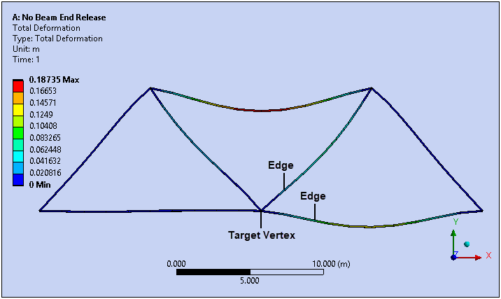
Deformation results for a pin-jointed beam-based truss are shown in the following illustrations. The loading is standard earth gravity. These examples illustrate some basic scoping scenarios.
Here is the Deformation with no End Release applied to the truss.
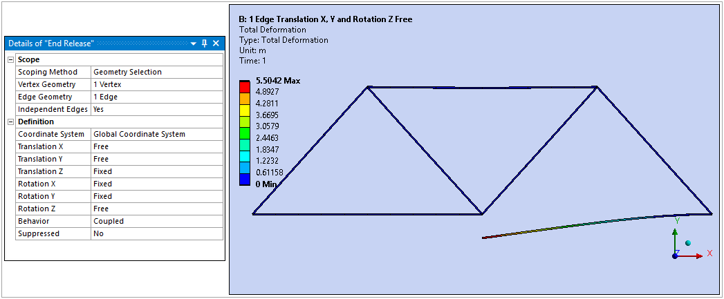
This illustration depicts the Deformation of the truss with an End Release applied to the vertex and one edge.
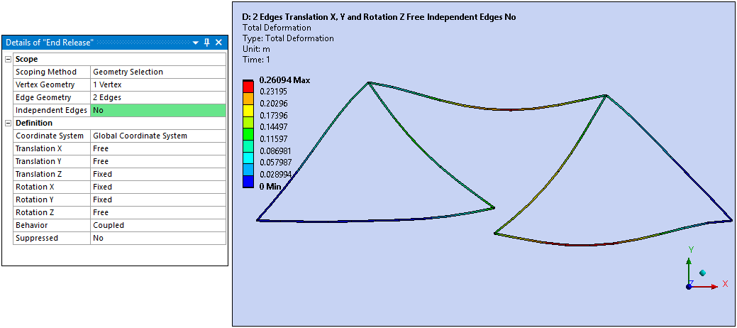
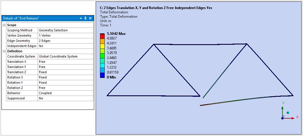
Here is the Deformation with an End Release applied to two independent edges.
Here is the Deformation with an End Release applied to the same two edges except that they are not independent.