


The feature allows for controlled and fully dimensioned placement of points relative to selected model faces and edges. These points are referred to as point feature points, or PF points.
Point topics:
Usage
The feature can operate on both active and frozen bodies. You begin by selecting the set of base faces and edges, or only line body guide edges. Next, select the type:
Spot Weld: Used for "welding" together otherwise disjointed bodies. Only those points that successfully generate mates are passed as Spot Welds to the Mechanical application.
Point Load: Used for "hard points" in the analysis. All points that successfully generate are passed to the Mechanical application as vertices. However, the Mechanical application will ignore points that do not lie on any body. Point loads on multibody parts are permitted.
Construction Point: No points of this type are passed to the Mechanical application.
Then, choose from up to five possible Point Definition options, and for each of these certain placement definitions may be specified:
Table 1: Point Definition Options
| POINT DEFINITION | AVAILABLE PLACEMENT DEFINITIONS |
|---|---|
| Single | Sigma and Offset |
| Sequence By Delta | Sigma, Offset, Delta |
| Sequence By N | Sigma, Offset, N, Omega |
| From Coordinates File | (See Coordinates File section below) |
| Manual Input (Construction Point only) | (See Manual Input section below) |
The Point placement is defined by distances on the chain of guide edges and by distances along the chain of guide edges as follows:
| Sigma: The distance between the beginning of the chain of guide edges and the placement of the first point. Measurement is taken on the chain of the first Guide Edge selected, in arc length. |
| Edge Offset: The approximate distance between the guide edges and the placement of the spots on the set of base faces (not applicable to line body guide edges). |
| Delta: The distance, measured on the guide edges, in arc length between two consecutive points, for the Sequence By Delta option. |
| N: The number of points to be placed, relative to the chain of guide edges, in case of the Sequence By N option. |
| Omega: The distance between the end of the chain of guide edges and the placement of the last spot, for the Sequence By N option. Measurement is taken on the chain of the Guide Edges in arc length. |

Definitions
Base Faces: Where points are to be added (only for non-line body guide edges). Base Faces are not applicable to create points on line body edges.
Guiding Edges: Used as a reference to create the points.
Mating Faces: What DesignModeler detects as the faces on which mating points are to be created when creating the "Spot Welds." This can be used to approximate "Seam Welds."
Non-line body guide edges: These faces may be on either side of the Base Faces within the given range. If the edge offset is zero (that is, if the points lie on the Guide Edges, and no Mating Faces are found on either side of the Base Face), then an attempt is made to find Mating Faces in the tangent direction of the Base Face.
Line body guide edges: The Mating face may be in any direction to the guide edge within the given range.
Mating Targets: What body is to be used for finding contact points. Used for models with multiple bodies, when contact is only desired between certain bodies.
The mating face is detected automatically, and the points are added depending on whether the mating face is above the points on the base face, or below the points on the base face. Illustrated below is an example when points will not have mating points on the Mating Face.

Point Placement
For edge offsets that are nonzero, the point is placed on a Base Face, relative to the Guiding Edge, as illustrated below.

| Location on Guiding Edge. |
| Point (1) is offset in direction perpendicular to Surface Normal and Edge Tangent. |
| Point (2) is projected back onto the face at the point on the surface closest to point (2). For planar faces, no projection is needed since point (2) will already lie on the face. |
Points that fall outside their base faces will not be placed, as illustrated below.

Note: The Edge Offset is not applicable to line body edges. In this case, points always will be placed on the selected line bodies.
If Sigma is zero, then the sequence of the points will begin from the beginning of the first edge of the chain of guide edges. Similarly, if Omega is zero, the point at the other end will be at the end of the last edge of the chain of guide edges.
For the Spot Weld analysis type, there is a "Range" property in the Details View. In this case, for each point placed on the base faces/guide edges, the system will attempt to find a suitable "mate" on another face (typically on another Surface body). If successful, it will then place a point at the "mate" position as well (the original point and its mate will be interpreted as a "weld" by the Mechanical application). The Range specifies the maximum distance for each original point to probe for its mate.
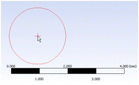
Note that in Edit Selections mode the mouse cursor is enclosed by a circle of diameter equal to the “Range” provided for the Spot Weld analysis type. This enables you to visualize the range in the model workspace (Graphics Window). No circle will be drawn if Range provided is 0. The image shows the cursor change when range value provided is 2 millimeter.
Point Mate Search Procedure

Points on Faces
For points on faces, mates are found by searching up to three directions:
The Surface Normal
The opposite direction of the Surface Normal
The direction perpendicular to both the Surface Normal and Edge Tangent
Direction 1 and 2 are always searched. The closest mate found from these two directions is chosen. If no mate is found, then direction 3 is searched.
Mate placement is defined by the ray originating from the original point in one of the three directions described above. Note that each point's ray may be different, since the ray depends on the shape of the base face, as illustrated below. The distance between the point and its mate must be less than or equal to the Range parameter. For a Spot Weld from Coordinates File, only directions 1 and 2 are searched. Also note that the placement of the mate may fail if the candidate face is tangential to the ray direction.

Points on Line Body
For points on line body, mates are found by searching around the point (360 degrees), in the normal direction to the guide edge at that point as shown in the figure below.
The closest mate found from the point will be chosen to create the mate point. However, the distance between the point and its mate must be less than or equal to the Range parameter.
Face Offset Property
This option allows you to place points offset from the surface of the base face. The Face Offset property is available for Point Load and Construction Point types, but not for Spot Welds. The offset direction is determined by the surface normal as shown here. The Face Offset Property is not supported for points created on line bodies as they are not attached with any faces.
The face offset may be either positive or negative, and may even result in the point being placed inside a body. An example is shown here, where the base face and guide edge are highlighted.
Current versions of the Mechanical application (up to and including 9.0) do not support isolated points, that is, points that are placed off a surface, be it inside or outside a solid. This means that currently you should not use Face Offsets > 0 for any other purpose than for creating construction points, internal to the Ansys DesignModeler model.
Coordinates File
This option allows you to specify a text file from which to read coordinates. These coordinates are used exactly as specified and are not projected onto any face or edge. The file itself must be a simple text file formatted according to the following rules:
After a pound sign '#,' everything else on that line is considered a comment and is ignored.
Empty lines are ignored.
Data consists of 5 fields, all on one line, separated by spaces and/or tabs:
Group number (integer): must be >0
Id number (integer): must be >0
X coordinate
Y coordinate
Z coordinate
A data line with the same Group and Id numbers as a previous data line is an error.
Number of points is limited to the value set in the Options dialog box (see the Point Feature Limit setting under the DesignModeler application's Miscellaneous settings in the Options dialog box).
Before generation, a unit for the coordinates and a base plane must be selected. The current session unit and the last plane selected will be used by default.
The Refresh property for this option allows you to update your text file and have the system read it again. Since the Group number and Id number fields uniquely identify each point generated for this Point feature, this allows you to modify coordinates, or delete or add points. A sample coordinates file is shown below.
# List of Point Coordinates

# Format is integer Group, integer ID, then X Y Z all
# delimited by spaces, with nothing after the Z value.

# Group 1
1  1  20.1234  25.4321  30.5678
1  2  25.2468  30.1357  35.1928
1  3  15.5555  16.6666  17.7777

#Group 2
2  1  50.0101   100.2021  7.1515
2  2  -22.3456  .8765     -.9876
2  3  21.1234   22.4321   23.5678
Note: The decimal separator format in the coordinates file should match the locale of the machine's operating system. Otherwise, the values from the coordinates file cannot be read properly.
Point Load and Spot Weld from Coordinates File Notations
For and , a base face or base edge in case the edge belongs to line body is searched for at each point, and for , mate faces are also determined. Because the mate faces are automatically detected, you should not put locations of mate points in the file. Doing so may result in the creation of duplicate spot welds.
Normally, a very tight tolerance is used when checking that a point is actually on a face or edge when the edge belongs to line body. For locations read from coordinates files, this tolerance is loosened to make the points easier to specify. However, they will still need to be within 5.0e -7 meters of the face. This tolerance is mapped to the unit setting you are using, so for example it is equivalent to 5.0e-4 millimeters, or about 2.0e-5 inches.
For points edges (not associated with line body), if a point lies on an edge or vertex, then any of the adjacent faces could be used for . will try each of these possible faces until it finds one for which it can also find a mate face. You have some control of this by selecting the Target Bodies in the Point feature.
For and , points are created for each coordinate in the file (up to the limit, see item five in Coordinates File). However, note that the Mechanical application will ignore points that are not on a face. Also, for , if no base face is found, the point is internally marked as "expired" and does not display or transfer to the Mechanical application.
Note: If a point is in contact with a suppressed body, the point will also be suppressed, and therefore will not be transferred to the Mechanical application. If you wish to transfer points to the Mechanical application, but not the underlying body, you must delete the underlying body instead of suppressing it.
Special Notes for PF Points in Regions of Shared Topology
DesignModeler allows the placement of PF Points on multibody parts, but you should be careful when placing them in a region of Shared Topology. When neighboring bodies are combined in a multibody part, sometimes edges and faces can disappear due to merging. If a PF Point is placed in a region where topology between bodies will be shared, there is a good chance the point will not appear in the Mechanical application when the model is transferred. The reason for this is that PF points reference specific face and edge geometry. If its face or edge gets merged away in the final part due to shared topology, then the PF point will not transfer to the Mechanical application. To ensure the PF Point makes it into the Mechanical application, it is advisable to place PF Points on both sides of the shared region.
Manual Input
This option allows you to create any number of Construction Points from a single Point feature by manually entering the coordinate values for each point. Each point group represents one point in Ansys DesignModeler. You can create as many point groups as you want in one Point feature.
Manual Input topics:
Other 3D features: