Takes a series of profiles from different planes to (Add, Cut, Slice, Imprint, or Add Frozen, depending on the chosen "material type") a solid or surface fitting through them. The Details View can be used to change the modeling operations (Add, Cut, Slice, Imprint, or Add Frozen). Solid, Surface, and thin-walled features can be created by using this feature. For creating a surface body, the inner and outer thickness values should be kept equal to zero. Clicking Generate completes the feature creation and updates the model.
You must select two or more profiles for the feature. A profile is a sketch with one closed or open loop or a plane from a face or a Named Selection or geometric entities such as faces, edges, vertices, etc. All profiles must have the same number of edges. Additionally, open and closed profiles cannot be mixed. All profiles for the Skin/Loft feature must be of the same type. Sketches and planes can be selected by clicking on their edges or points in the graphics area, or by clicking on the sketch or plane branch in the Tree Outline. Upon selecting an adequate number of profiles, a preview will appear which shows the selected profiles and the guide line only if they have the same number of edges and they are not mixed profiles.
The Profile Selection Method property has two options, "Select All Profiles" and "Select Individual Profile". When you are in the "Select All Profiles" method you can select the profiles using "Profiles" property. Each Sketch, Named Selection feature and each open, closed and acorn chain obtained from geometric entities will go to an individual profile group. When you are in the "Select Individual Profile" method, the "Profiles" property will not be visible. Instead, you can edit each individual profile group. You can add/insert new profile groups and delete existing profile groups as illustrated below. When you select a group in the Details View, the entities present in that group will be shown in cyan and entities of other groups will be shown in magenta.
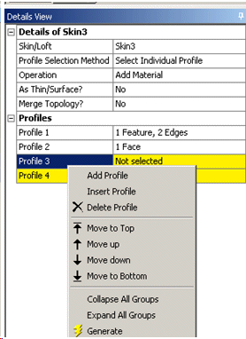
Skin/Loft Context Menu Options
There is a right mouse button Context Menus to assist in creating the feature. Clicking the right mouse button context menu will present two options:
Fix Guide Line: The guide line is a gray polyline that defines how the vertices of the profiles line up with each other throughout the Skin/Loft. Selecting this option will place you in an alignment mode where you can click on vertices in the graphics area to change the guide line’s path through the profiles. Generally, select the vertices such that the guide line flows smoothly from one profile to the next. When the guide line twists from one profile to the next, it will result in a twisted Skin/Loft that may not generate. Below is an example of straight and twisted guide lines and their corresponding result. For open profiles, the guide line must pass through the profiles at their endpoints. For point profiles, there is no need to adjust the guide line through them as they only contain a single point.
Outline planes (represented by gray lines) can be aligned by setting the Selection Filter (accessible via the right mouse button) to 2D Edge. When you select 2D Edge on the outline planes, the starting point of the selected edges will be used to show the guide line alignment.
Note: The "Fix Guide Line" option will not be available when you are editing entries present in the profile group.
Example 25: Guide line with consistent alignment
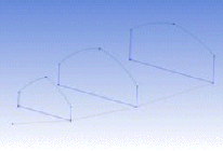
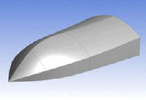
Guide line with consistent alignment through the profiles and the resulting smooth Skin/Loft.
Example 26: Guide line with twisted alignment
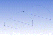
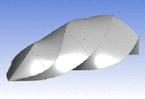
Guide line with twisted alignment through the profiles and the resulting twisted Skin/Loft.
Continue Sketch Selection: Leaves the alignment state to continue profile selection for the Skin/Loft feature.
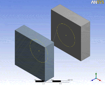
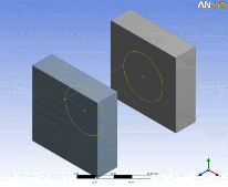
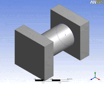
Full circles or ellipses can present problems if they are defined on planes facing roughly in opposite directions. The Skin/Loft feature can fail if the parameterization of the two curves causes the result to become twisted. When a profile has no endpoints, the feature will internally imprint a vertex on the edge. The vertex is placed at the start point of the edge’s underlying curve. If two profiles are facing each other, the imprinted points can often end up on opposite sides of the profiles, which will cause the Skin/Loft to fail due to a self intersection. A workaround for this is to introduce a vertex on the profiles so they can be used to align the feature’s guide line. This can be done in several ways:
Splitting the sketch edge: Use the Split sketching tool to split the profiles into two or more segments, or split the profile at a single location, which will introduce a single vertex on the resultant profile.
Split Edges feature: If using Named Selections as profiles, you can split the edge into several pieces using this feature before using it in the Skin/Loft operation.
Skin Profile Ordering
Profiles are reordered through the Details View. The Skin/Loft feature's Details View will list the selected profiles in order. If you select a profile and then click the right mouse button, a context menu Context Menus appears which allows you to reorder that profile's position in the list, as illustrated below.
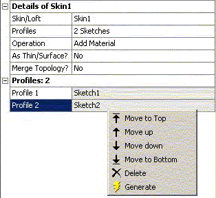
There are four reordering options plus , which will remove the selected profile from the list altogether.
Point Profiles
The feature can accept profiles consisting of a single point. A point profile is defined as a sketch that contains exactly one construction point and nothing else or a Named Selection with a single vertex or 3D Point (from Point feature). Point profiles are restricted to either the first and/or last profile in the profile list. Point profiles may not be placed in the middle of the profile list. If both the start and end profiles are point profiles, then at least three profiles are necessary for the feature instead of the usual two and the third profile must be a non-point profile kept in the middle of the sequence. You can tell which profiles in the Details View are point profiles by the asterisk (*) that is placed after them. In the following picture, Sketch3 is a point profile:

You do not need to be concerned about how the guide rail lines up with a point profile, since there is only a single point for the to which to converge. The other profiles in your profile list may be either open or closed, but not both. Shown here are some examples:
Profiles for a boat's hull (closed profiles): 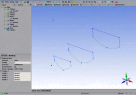 | After generating the Skin/Loft: 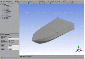 |
Profiles for a surface (open profiles): 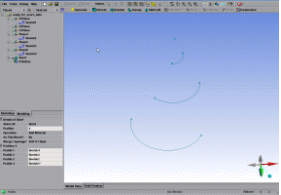 | After generating the Skin/Loft: 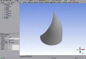 |
Note: When performing Skin/Loft operations with point profiles at the end and circular or elliptical profiles throughout the middle, DesignModeler may not be able to generate a walled feature due to a geometry singularity at the tip of the resultant body.
Other 3D features:


