The feature allows you to create planar transitions (or chamfer faces) across model edges. This feature can be executed on both frozen and active bodies beginning in version 11.0. Prior to version 11.0, this feature would only operate on active bodies.
You can preselect 3D edges and/or faces for chamfering, and/or you can select 3D edges and/or faces while in the chamfer creation itself. If a face is selected, all the edges from that face are chamfered. Preselection allows additional options from a right mouse button context menu for face edge loop selection and smooth 3D edge chain selection from the model. Every edge on a face has a direction. This direction defines a right and left side.
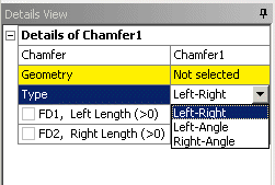
is defined either by two distances from the edge for the planar transition (chamfer face), or by a distance (left or right) and an angle. The type of chamfer is defined in the Details View along with the distances and angle. Clicking Generate completes the feature creation and updates the model.

Calculating the Chamfer Location
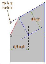
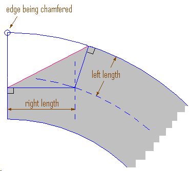
When specifying the left and right lengths, the left and right sides of the edge are determined based on the edge orientation. The face on the right side of the edge is offset by the right length and the face on the left side is offset by the left length. The intersection curve of these offset surfaces is projected on the corresponding faces. Such a projection of the intersection curve onto the right and left faces determines the extent to which the body will be chamfered.
Example 29: The effect of Left and Right length
Chamfer of an edge of faces meeting at an angle.  | Chamfer of an edge of non-planar face.  |
Other 3D features:


