


The Weld Feature is used to create Weld Bodies that represent the weld created between two bodies. There can be multiple Weld groups in each Weld feature.
Each group takes one or more edges and faces as source and target entities, respectively. The weld body will be created from the selected edges up to the bounding target faces selected. Multiple edges can be selected in a group from which edge chains will be prepared. Each edge chain will be a set of connected edges belonging to a single body.
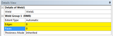
Extent Type
The Extent Type property defines three types of extension; Automatic, Natural and Projection. The default option is Automatic.
Automatic
If the Extent Type is Automatic, which is the default extent type, then the weld body is created by first using the Natural extension type and if it fails, then Projection extension type is used.
Natural
If the Extent Type is Natural, then the weld body is created as if the surface owning the input edge is extended along the selected edge up to the target faces selected. The input edges must be laminar edges of surface bodies for the weld to succeed in the Natural extension type.
Projection
If the Extent Type is Projection, then the weld body is created by initially projecting the input edges on the target faces and then a surface is fitted through the input edges and the projected edges. The input edges can belong either to surface or solid.
The weld body created will be in a frozen state and will belong to the same part of the parent body to which the selected edges belong to.
Edges
Edges is an Apply/Cancel button property that facilitates the selection of the edge sets. The selected edges must be on the boundary of the surface for natural extent type. Edges of Solid body and on the interior of the Surface body can be selected for Projection extent type.
Faces
Faces is an Apply/Cancel button property that facilitates the selection of the face sets, based on which weld body will be created up to a bounding set of faces.
Example 64: Natural
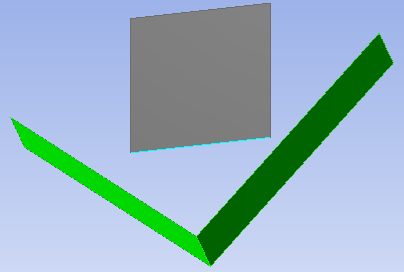
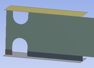
The following example demonstrates the Projection Weld formation. First, select the edges along the surface to create a weld body. Next, select the faces as shown in the figure below.
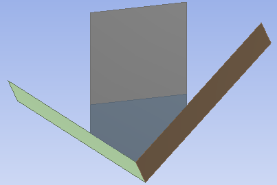
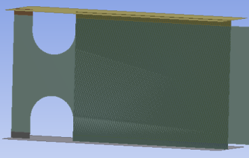
Upon generation, the weld body is created as shown:
Example 65: Projection
The following example demonstrates the Projection Weld formation. First, select the edges along the surface to create a weld body. Next, select the faces as shown in the figure below.
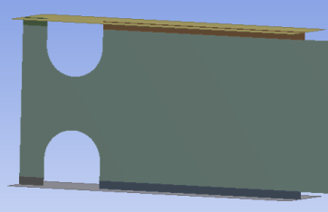
Upon generation, the weld body is created as shown:
Projection Extent Type Limitation
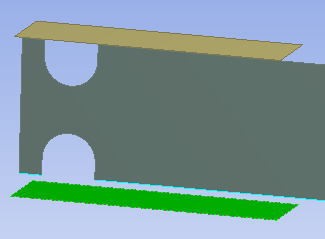
If the top edges are also selected apart from the bottom edges as shown above and also the top face apart from the bottom face, then the result would be as shown below:
Here, you can see that a few additional weld bodies are created as it tries to create weld bodies for input edges to all selected target faces, this is a limitation and it is recommended to create separate weld groups with distinct input edges to obtain the intended results. If you select the top edges and top face in one weld group and the bottom edges and bottom face in another weld group, then the result would be as shown below:
Thickness Mode
The thickness propagation in the newly created weld body is controlled by Thickness Mode. It has two values; Inherited and User Defined.
Inherited: — indicates that the newly created weld body will get the thickness value from the parent body to which the input edge belongs to. When the Thickness Mode is set to Inherited, the Thickness property will be read-only.
User Defined: — indicates that the thickness of the newly created weld body can manually be modified and the thickness value will be retained, even if you regenerate the feature. You can manually change the thickness value only if the Thickness Mode is set to User Defined.