


The mesh checking capability in Ansys Fluent examines various aspects of the mesh,
including the mesh topology, periodic boundaries, simplex counters, and (for axisymmetric
cases) node position with respect to the  axis, and provides a mesh check report with details about domain extents,
statistics related to cell volume and face area, and information about any problems associated
with the mesh. You can check the mesh by clicking the button in
the General task page.
axis, and provides a mesh check report with details about domain extents,
statistics related to cell volume and face area, and information about any problems associated
with the mesh. You can check the mesh by clicking the button in
the General task page.
![]() Setup →
Setup → ![]() General
→ Check
General
→ Check
Important: It is generally a good idea to check your mesh right after reading it into Fluent, in order to detect any mesh trouble before you get started with the problem setup.
The mesh check examines the topological information, beginning with the number of faces and nodes per cell. A triangular cell (2D) should have 3 faces and 3 nodes, a tetrahedral cell (3D) should have 4 faces and 4 nodes, a quadrilateral cell (2D) should have 4 faces and 4 nodes, and a hexahedral cell (3D) should have 6 faces and 8 nodes. Polyhedral cells (3D) will have an arbitrary number of faces and nodes.
Next, the face handedness and face node order for each zone is checked. The zones should contain all right-handed faces, and all faces should have the correct node order.
The last topological verification is checking the element-type consistency. If a mesh does not contain mixed elements (quadrilaterals and triangles or hexahedra and tetrahedra), Ansys Fluent will determine that it does not need to keep track of the element types. By doing so, it can eliminate some unnecessary work.
For axisymmetric cases, the number of nodes below the  axis is listed. Nodes below the
  axis are forbidden for axisymmetric cases, since the axisymmetric cell
volumes are created by rotating the 2D cell volume about the
axis are forbidden for axisymmetric cases, since the axisymmetric cell
volumes are created by rotating the 2D cell volume about the  axis; therefore nodes below the
  axis would create negative volumes.
For solution domains with rotationally periodic boundaries, the minimum, maximum, average, and prescribed periodic angles are computed. A common mistake is to specify the angle incorrectly. For domains with translationally periodic boundaries, the boundary information is checked to ensure that the boundaries are truly periodic.
Finally, the simplex counters are verified. The actual numbers of nodes, faces, and cells that Fluent has constructed are compared to the values specified in the corresponding header declarations in the mesh file. Any discrepancies are reported.
When you click the button in the General task page, a mesh check report will be displayed in the console. The following is a sample of a successful output :
 Mesh Check

 Domain Extents:
   x-coordinate: min (m) = -4.000000e-002, max (m) = 2.550000e-001
   y-coordinate: min (m) = 0.000000e+000, max (m) = 2.500000e-002
 Volume statistics:
   minimum volume (m3): 2.463287e-009
   maximum volume (m3): 4.508038e-007
    total volume (m3): 4.190433e-004
   minimum 2d volume (m3): 3.000589e-007
   maximum 2d volume (m3): 3.019523e-006
 Face area statistics:
   minimum face area (m2): 4.199967e-004
   maximum face area (m2): 2.434403e-003
 Checking mesh.......................
Done.
The mesh check report begins by listing the domain extents. The domain extents include
the minimum and maximum  ,
,  , and
, and  coordinates in meters.
Then the volume statistics are provided, including the minimum, maximum, and total cell
volume in  . A negative value for the minimum volume indicates that one or more cells
have improper connectivity. Cells with a negative volume can often be identified and viewed
by creating an iso-value field variable cell register (Field Variable). You can try adapting the mesh to resolve
the negative volume cells (Adapting the Mesh). You
must eliminate these negative volumes before continuing the flow
solution process.
. A negative value for the minimum volume indicates that one or more cells
have improper connectivity. Cells with a negative volume can often be identified and viewed
by creating an iso-value field variable cell register (Field Variable). You can try adapting the mesh to resolve
the negative volume cells (Adapting the Mesh). You
must eliminate these negative volumes before continuing the flow
solution process.
Next, the mesh report lists the face area statistics, including the minimum and maximum
areas in  . A value of 0 for the minimum face area indicates that one or more cells
have degenerated. As with negative volume cells, you must eliminate
such faces. It is also recommended to correct cells that have nonzero face areas, if the
values are very small.
. A value of 0 for the minimum face area indicates that one or more cells
have degenerated. As with negative volume cells, you must eliminate
such faces. It is also recommended to correct cells that have nonzero face areas, if the
values are very small.
Besides the information about the domain extents and statistics, the mesh check report will also display warnings based on the results of the checks previously described. You can specify that the mesh check report displays more detailed information about the various checks and the mesh failures, by using the following text command prior to performing the mesh check:
mesh → check-verbosity
You will then be prompted to enter the level of verbosity for the mesh check report. The possible levels include:
0This is the default level, and only notifies you that checks are being performed (for example, Checking mesh...). The report will look like the previous example; while warnings will be displayed below the domain extents and statistics, the names of the individual checks will not be listed as they are conducted.
1This level lists the individual checks as they are performed (for example, Checking right-handed cells). Any warnings that result will be displayed immediately below the check that produced it.
2This level provides the maximum information about the mesh check. The report will list the individual checks as they are performed (for example, Checking right-handed cells); any warnings that result will be displayed immediately below the check that produced it. Additional details about the check failure will also be displayed, such as the location of the problem or the affected cells.
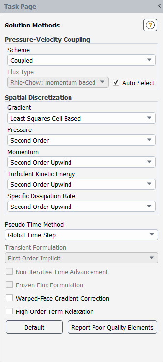
If the mesh check report indicates a mesh problem or if you receive warnings, you can investigate the extent of the problem by printing the poor element statistics in the console. This can be accomplished using the button, located at the bottom of the Solution Methods task page (Figure 6.83: The Solution Methods Task Page). Note that this button is only available when poor quality elements have been detected by the mesh check or have been marked for the application of poor mesh numerics (for details, see Robustness with Meshes of Poor Quality).
Alternatively, you can print the poor element statistics via the following text command:
mesh → repair-improve
→ report-poor-elements
You can also visualize the invalid and poor elements by marking and displaying them by using the Mesh... and Mark Poor Elements selections from the Field Value of drop-down lists of the Field Variable Register dialog box (see Field Variable for further details). Similarly, you can display them using the Contours dialog box, by selecting Mesh... and Mark Poor Elements from the Contours of drop-down lists.
The solver variable can take a value of 1 to 6 and can be visualized:
1.0 user_defined_poor_elements
2.0 poor_quality_cells
3.0 modified_centroid_cells
4.0 cell adjacent to small_face_area
5.0 invalid_cells
6.0 solver_identified_poor_cells
By default 3.0, 4.0 and 5.0 are active. 2.0 is recommended.
The mesh check report will indicate if the mesh has problems that must be repaired, such as left-handed faces and/or faces that have the wrong node order. If repairable failures are detected by the mesh check, the button in the Domain ribbon tab (Mesh group box) becomes available:
![]() Domain → Mesh
→ Repair
Domain → Mesh
→ Repair
Using the button is the simplest way to attempt to correct your mesh problems. It will attempt to correct a number of problems identified by the mesh check, including cells that have:
the wrong node order
the wrong face handedness or that are not convex
faces that are small or nonexistent
very poor quality (see Mesh Quality for additional details)
Note that by default, the button will only adjust the positions of interior nodes. If you want to also modify the nodes on the boundaries of the mesh, use the following text command before you repair the mesh:
mesh → repair-improve
→ allow-repair-at-boundaries
The button may convert degenerate cells into polyhedra, based on skewness criteria (for more information on how cells are converted, see Converting Skewed Cells to Polyhedra). If you want to ensure that there are no polyhedra in the repaired mesh (for example, if you if plan on performing hanging node adaption), you must disable such conversions using the following text command before you repair the mesh:
mesh → repair-improve
→ include-local-polyhedra-conversion-in-repair
If you would like to only attempt to improve the poor quality cells, you can use the following text command:
mesh → repair-improve
→ improve-quality
You can use the improve-quality text command multiple times,
until the mesh is improved to your satisfaction. For greater control over the degree to
which the mesh is improved, you can perform quality-based smoothing (as described in Smoothing).
It should be noted that both the button and the
improve-quality text command can be CPU intensive, if there are a
large number of poor quality cells in the mesh. If you are not as concerned about cell
quality, you can attempt to fix only the left-handed faces and faces with the wrong node
order. Begin by repairing the node order with the following text command:
mesh → repair-improve
→ repair-face-node-order
Because the left-handed faces may be a result of improper face node order, the previous
text command may resolve both issues at the same time. Be sure to perform another mesh check
after entering the repair-face-node-order command, to see if the
mesh has been fully repaired.
If at any point the mesh check reveals that the mesh contains left-handed faces without any node order issues, you can attempt to repair the face handedness by modifying the cell centroids with the following text command:
mesh → repair-improve
→ repair-face-handedness
Once again, perform a mesh check to see if the text command was successful. The
repair-face-handedness text command is most effective for cells
with high aspect ratios.
If the mesh check report includes a warning message such as
WARNING: node on face thread 2 has multiple shadows.
it indicates the existence of duplicate shadow nodes. This error occurs only in meshes with periodic-type walls. You can repair such a mesh using the following text command:
mesh → repair-improve
→ repair-periodic
If the interface is rotationally periodic, you will be prompted for the rotation angle.