The direct-embedding workflow uses standard structural, thermal, and coupled-field elements to model the embedded members and base elements.
The following topics are available for direct embedding:
Mechanical APDL assumes that the embedded elements and the base elements are bonded at the cross-sections of embedded elements nodes. Although the connections between the cross-sections of the embedded members and the base material are assumed to be bonded, some connection flexibilities including warping and section area changes are allowed.
Because the bonded connections are established at the embedded element nodes only, refined embedded elements may be required to guarantee the secure bonding of embedded and base elements.
The connection constraints are modeled with special-purpose REINF265 reinforcing elements (created automatically). For structural problems, the special-purpose REINF265 elements contribute no additional structural stiffness, mass, or external forces. For thermal problems, they contribute no additional thermal conduction, damping, or external heat.
The stiffness or external load on the overlapped regions occupied by both the embedded and base elements can be over-estimated due to the base material not being subtracted. For solution accuracy, the stiffness of the embedded elements is assumed to be larger than that of the base elements. Similarly, in a thermal analysis, embedded elements are assumed to have higher thermal conductivity than that of the base elements. In an electrical analysis, embedded elements are assumed to have lower electrical resistivities than that of the base elements.
Following are the element types supported for embedding and their base element types. "Y" indicates a valid combination of embedded and base elements, and "-" indicates an invalid combination. Only the common degrees of freedom of embedded and base elements are connected.
Table 14.3: Supported Elements for Direct Embedding
| Embedded Element Type | Base Element Type | ||||
| SOLID185, SOLID186, SOLID187, SOLID285 | SOLID278, SOLID279, SOLID291 | SOLID225, SOLID226, SOLID227 | |||
| KEYOPT(1) = 11 | KEYOPT(1) = 110 | KEYOPT(1) = 111 | |||
| LINK180 | Y | - | Y | - | Y |
| BEAM188, BEAM189 | Y | - | Y | - | Y |
| LINK33 | - | Y | Y | Y | Y |
| LINK228 KEYOPT(1) = 11 | Y | Y | Y | Y | Y |
| LINK228 KEYOPT(1) = 110 | - | Y | Y | Y | Y |
| LINK228 KEYOPT(1) = 111 | Y | Y | Y | Y | Y |
| LINK228 KEYOPT(1) = 101 | Y | - | Y | Y | Y |
| LINK228 KEYOPT(1) = 1001 | Y | - | Y | - | - |
All features of the supported base element types are available with these exceptions:
Following is the direct element-embedding process:
Create the base elements and the elements to be embedded.
Select the base elements and the elements to be embedded.
Optional step: If required, optimize the base elements according to the elements to be embedded. For more details about the requirements and limitations, refer to the MSHOPTIM command.
Embed the elements (EEMBED).
Inspect and verify the connections.
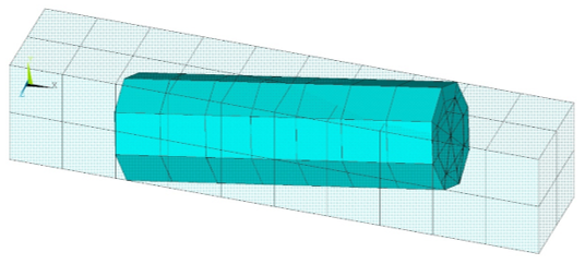
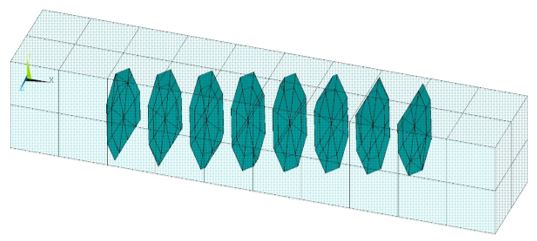
As shown in the following input example, you can adjust the translucency of the base elements to show the special-purpose REINF265 elements representing the bonded connection between the base and embedded elements:
Example 14.11: Defining Element Embedding
/batch,list
/title, Example input data for element embedding
/prep7
!
! Define material properties
!
mp,nuxy,1,0.3   ! base material
mp,ex,1,1e6
mp,nuxy,2,0.3   ! embedded material
mp,ex,2,1e9
!
! Define base elements
!
et,1,185
mat,1
block,0,10,-1,1,-1,1
esize,1
vmesh,1
!
! Define beam elements to be embedded
!
et,2,188
sect,2,beam,csolid
secd,1
k,101,2,-0.5,
k,102,8,0.5
l,101,102
lesize,all,1,
secn,2
mat,2
type,2
lmesh,13
!
! Inspect BEAM and base SOLID elements
!
esel,s,type,,1
/trlcy,elem,0.9
esel,all
/eshap,1
/view,1,1,2,3
! Activate the expanded element shapes
/eshape,1
/show,png,rev,,8,'beam_and_solid_elements'
eplot
/show,close
!
! Create element embedding
!
eembed
!
! Inspect newly created reinforcing elements
!
esel,u,ename,,188
/show,png,rev,,8,'reinf_and_base_elements'
eplot
/show,close
The input listing in Example 14.11: Defining Element Embedding generates the following output: