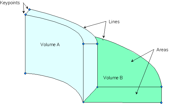
Any solid model, whether assembled from the bottom up or from the top down, is defined in terms of keypoints, lines, areas, and volumes. Figure 5.9: Basic Solid Model Entities illustrates these entities.
Keypoints are the vertices, lines are the edges, areas are the faces, and volumes are the interior of the object. Notice that there is a hierarchy in these entities: volumes, the highest-order entities, are bounded by areas, which are bounded by lines, which in turn are bounded by keypoints.
Caution: Solid modeling operations in a toroidal coordinate system are not recommended. Areas or volumes generated may not be what you expect.
In bottom up construction, you first create keypoints and use those keypoints to define higher-order solid model entities (lines, areas, and volumes).
When building your model from the bottom up, you begin by defining the lowest-order solid model entities, keypoints. Keypoints are defined within the currently active coordinate system. You can then define lines, areas, and volumes connecting these keypoints. You do not always have to explicitly define all entities in ascending order to create higher-order entities: you can define areas and volumes directly in terms of the keypoints at their vertices. The intermediate entities will then be generated automatically as needed. For example, if you define a brick-like volume in terms of the eight keypoints at its corners, the program will automatically generate the bounding areas and lines.
To define individual keypoints, use one of the methods listed in the following table. See the Command Reference for more information on the individual commands.
| Define a Keypoint | Command |
|---|---|
| in the active coordinate system | K |
| at a given location on an existing line | KL |
Once you create an initial pattern of keypoints, you can generate additional keypoints and work with existing keypoints using the methods described in the following table. Many Boolean operations (see Sculpting Your Model with Boolean Operations) will also create keypoints.
| Command | |
|---|---|
| create a keypoint between two existing keypoints | KBETW |
| generate keypoints between two keypoints | KFILL |
| create a keypoint at the center of a circular arc defined by three locations | KCENTER |
| generate additional keypoints from a pattern of keypoints | KGEN |
| generate a scaled pattern of keypoints from a given keypoint pattern | KSCALE |
| generate a reflected set of keypoints | KSYMM |
| transfer a pattern of keypoints to another coordinate system | KTRAN |
| define a default location for undefined nodes or keypoints | SOURCE |
| calculate and move a keypoint to an intersection | KMOVE |
| define a keypoint at an existing node location | KNODE |
| calculate the distance between two keypoints | KDIST |
| modify the coordinates defining a keypoint [1] | KMODIF |
Modifying the coordinates will automatically clear any meshed region attached to the specified keypoint, and will also redefine the higher-order entities attached to that keypoint. (A keypoint can also be redefined using the K command, but only if it is still "free." That is, the keypoint is not yet attached to a line or meshed.)
You can maintain keypoints using the methods listed in the following table.
| Maintenance | Command |
|---|---|
| list defined keypoints | KLIST |
| select keypoints | KSEL |
| display selected keypoints | KPLOT |
| delete unmeshed keypoints | KDELE |
If you have issued the command /PNUM,KP,1, keypoint numbers will also appear in line, area, and volume displays (LPLOT, APLOT, and VPLOT) for keypoints attached to these higher-order entities.
Hard points are actually a special type of keypoints. You can use hard points to apply loads or obtain data from arbitrary points on lines and areas within your model. Hard points do not modify either the geometry or topology of your model. Most of the keypoint commands, such as FK, KLIST, and KSEL, can be applied to hard points. In addition, hard points have their own set of commands and extension in the GUI.
If you issue any commands that update the geometry of an entity, such as Boolean or simplification commands, any hard points associated with that entity are deleted. Therefore, you should add any hard points after completing the solid model. If you delete an entity that has associated hard points, those hard points are either
Deleted along with the entity (if the hard point is not associated with any other entities).
Detached from the deleted entity (if the hard point is associated with additional entities).
You cannot manipulate hard points with commands to copy, move, modify, or modify keypoints. Hard points have their own suite of commands and GUI controls. Mapped meshing is not supported when hard points are used. Hard point information cannot be written to the IGES file. The Jobname.cdb file can be written with the CDWRITE,DB option.
You can define hard points on existing lines or areas. In both cases, you can define the location of hard points on such entities by
Picking (unavailable for models imported from IGES files).
Specifying ratios (available for lines only).
Specifying global X, Y, and Z coordinates.
To create hard points, use one of the methods listed in the following table.
| Define individual hard points | Command |
|---|---|
| on an existing line | HPTCREATE, LINE |
| on an existing area | HPTCREATE, AREA |
You can select hard points or geometric entities with associated hard points using any of the methods described in the following table.
| Select | Command |
|---|---|
| hard points | KSEL |
| lines with associated hard points | LSEL |
| areas with associated hard points | ASEL |
You can maintain hard points using the methods described in the table below.
Lines are mainly used to represent the edges of an object. As with keypoints, lines are defined within the currently active coordinate system. You do not always need to define all lines explicitly, because the program will generate the necessary lines in many instances when an area or volume is defined. Lines are required if you want to generate line elements (such as beams) or to create areas from lines.
If you need to explicitly define a line, you can use one of the methods described in the following table.
| Generate a | Command |
|---|---|
| "straight" or cubic line between two specified keypoints | L |
| circular line through three keypoints (or between two keypoints if you specify a radius) | LARC |
| cubic line from a spline fit to a series of keypoints | BSPLIN |
| circular arc line | CIRCLE |
| segmented spline through a series of keypoints | SPLINE |
| straight line at an angle with a line | LANG |
| line at an angle with two existing lines | L2ANG |
| line at the end of, and tangent to, an existing line | LTAN |
| line tangent to two lines | L2TAN |
| shortest line between two keypoints on an area | LAREA |
| line by sweeping a keypoint pattern along a path [1] | LDRAG |
| circular line by rotating a keypoint pattern about an axis | LROTAT |
| fillet line between two intersecting lines | LFILLT |
| truly straight line no matter what coordinate system is active | LSTR |
For best results when using drag operations (LDRAG), minimize the distance (shown as distance "d" in Figure 5.10: Drag Operation Suggestions) from the drag path plane to the entities to be dragged. Also the entity plane should be as close to parallel to the drag path plane as possible. Both of these guidelines can be met if the entities to be dragged are in the drag path plane. The drag path plane is automatically defined to be orthogonal to and located at the start of the drag path.
For those commands that create a "straight" line, the actual shape of the line will be determined by the active coordinate system. Thus, for a "straight" line in a Cartesian coordinate system, dX/dL, dY/dL, and dZ/dL will each be constant along the length (L) of that line, producing a line that is truly straight. For a "straight" line in a cylindrical coordinate system, dR/dL, dθ/dL, and dZ/dL will each be constant, producing a line that could be a helical spiral (if all three components of slope were nonzero).
Copy a pattern of lines to generate additional lines using any of the methods described in the following table.
| Command | |
|---|---|
| generate additional lines from a pattern of lines | LGEN |
| generate lines from a line pattern by symmetry reflection | LSYMM |
| transfer a pattern of lines to another coordinate system | LTRAN |
You can modify an existing line by redefining it (by reissuing the L command) or by using one of the methods described in the following table.
| Modification | Command |
|---|---|
| divide up a line into smaller lines | LDIV |
| combine a line with a second line | LCOMB |
| extend a line at one end | LEXTND |
You can also use several geometric primitives and Boolean commands to generate or modify lines. See Creating Your Solid Model from the Top Down: Primitives for more information on geometric primitives and Sculpting Your Model with Boolean Operations for more information on Boolean operations.
You can maintain lines using the methods listed in the following table.
Only unmeshed lines that are not attached to an area can be redefined, modified, or deleted. LDIV, LCOMB, and LFILLT provide exceptions to this rule. You can use these three commands to modify unmeshed lines, even if they are attached to areas. The attached areas will be updated, even if they are attached to volumes.
If you have issued the command /PNUM,Line,1, line numbers will also appear in area and volume displays (APLOT and VPLOT) for lines that are attached to these higher-order entities.
Flat areas are used to represent 2D solid objects (such as flat plates or axisymmetric solids). Curved as well as flat areas are used to represent 3D surfaces, such as shells, and the faces of 3D solid objects. Areas are required if you wish to use area elements or if you wish to create volumes from areas. Most commands that create areas will also automatically generate the necessary lines and keypoints. Similarly, many areas can be conveniently generated by defining volumes.
You can use any of the methods described in the following table to explicitly define areas. Several geometric primitives and Boolean commands can also be used to generate or modify areas. See Creating Your Solid Model from the Top Down: Primitives for more information on geometric primitives and Sculpting Your Model with Boolean Operations for more information on Boolean operations.
| Define an area | Command |
|---|---|
| in terms of its vertices (through keypoints) | A |
| in terms of its boundaries (a set of lines defining the perimeter) | AL |
| by "sweeping" a line along a characteristic path [1] | ADRAG |
| by rotating a line pattern about an axis | AROTAT |
| of constant fillet radius at the intersection of two areas [2] | AFILLT |
| by "skinning" a surface through guiding lines | ASKIN |
| by offsetting an existing area (similar to what happens when a balloon is inflated or deflated) [3] | AOFFST |
For best results when using drag operations (ADRAG), minimize the distance (shown as distance "d" in Figure 5.10: Drag Operation Suggestions) from the drag path plane to the entities to be dragged. Also the entity plane should be as close to parallel to the drag path plane as possible. Both of these guidelines can be met if the entities to be dragged are in the drag path plane. The drag path plane is automatically defined to be orthogonal to and located at the start of the drag path.
You might experience difficulties due to the underlying Boolean operations used by this command. You may wish to use rotate or extrude operations (VROTAT or VEXT) to perform the same operations. See When a Boolean Operation Fails for additional information.
You might experience difficulties if you attempt to "deflate" an area by a distance that equals or exceeds its least radius of curvature. Using this process will not generate a new surface when such problems arise (you will receive a warning if the process fails).
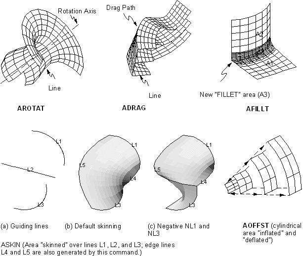
Figure 5.11: Area Command Operations for examples of the operations you can perform with the AROTAT, ADRAG, AFILLT, ASKIN, and AOFFST commands.
You can copy existing areas to generate additional areas using the methods described in the following table. Several geometric primitives and Boolean commands can also be used to generate or modify areas. See Creating Your Solid Model from the Top Down: Primitives for more information on geometric primitives and Sculpting Your Model with Boolean Operations for more information on Boolean operations.
| Command | |
|---|---|
| Generate additional areas from a pattern of areas | AGEN |
| Generate areas form an area pattern by symmetry reflection | ARSYM |
| Transfer a pattern of areas to another coordinate system | ATRAN |
| Copy a portion of an area | ASUB |
Use the methods listed in the following table to maintain areas. Only unmeshed areas that are not attached to a volume can be redefined or deleted.
| Maintenance | Command |
|---|---|
| List defined areas [1] | ALIST |
| Display areas | APLOT |
| Select areas | ASEL |
| Delete areas | ADELE |
The area (topographical measure) of an area (solid model entity) will be included in an ALIST only if you previously executed ASUM (). The "loop" numbers shown refer to the closed strings of lines that define the boundaries of an area, as illustrated in Figure 5.12: Loops Bound an Area.
NO.LOOP      LINES               AREA      #NODES #ELEM   MAT  REAL  TYP ESYS
  1  1     1     2     3     4   N/A            0     0     0     0    0    0
     2    12    13    11
     3     5    10     9     8
7 6Volumes are used to represent 3D objects, and are required only if you wish to use volume elements. Most commands that create volumes will also automatically generate the necessary lower-order entities.
To define volumes, use any of the methods described in the following table. Several geometric primitives and Boolean commands can also be used to generate or modify areas. See Creating Your Solid Model from the Top Down: Primitives for more information on geometric primitives and Sculpting Your Model with Boolean Operations for more information on Boolean operations.
| Define a volume | Command |
|---|---|
| in terms of its vertices (through keypoints) | V |
| in terms of its boundaries (in terms of a set of areas defining the surfaces) | VA |
| by "sweeping" an area pattern along a characteristic path [1] | VDRAG |
| by rotating an area pattern about an axis | VROTAT |
| by offsetting an area | VOFFST |
| by extruding and scaling a pattern of areas in the active coordinate system | VEXT |
For best results when using drag operations (VDRAG), minimize the distance (shown as distance "d" in Figure 5.10: Drag Operation Suggestions) from the drag path plane to the entities to be dragged. Also the entity plane should be as close to parallel to the drag path plane as possible. Both of these guidelines can be met if the entities to be dragged are in the drag path plane. The drag path plane is automatically defined to be orthogonal to and located at the start of the drag path.
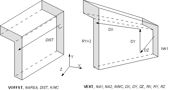
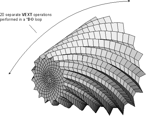
Figure 5.13: Volume Command Operations illustrates the VOFFST and VEXT command operations.
To generate additional volumes from existing volumes, use the methods described in the following table.
| Generate volumes | Command |
|---|---|
| from a pattern of volumes | VGEN |
| from a volume pattern by symmetry reflection | VSYMM |
| transfer a pattern of volumes to another coordinate system | VTRAN |
You can maintain volumes using the methods described in the following table. Note that only unmeshed volumes can be redefined or deleted.
| Maintenance | Command |
|---|---|
| list volumes [1] | VLIST |
| display volumes | VPLOT |
| select volumes | VSEL |
| delete volumes | VDELE |
If the area that is being extruded (used as the pattern for the resulting volume) with the VROTAT, VEXT, VOFFST, or VDRAG command is meshed (or belongs to a meshed volume), that mesh will be used as a pattern for the mesh of the volume that is created. (Compare these commands to the VSWEEP command, which is described in Sweeping Volumes.)
Follow these steps to extrude your mesh:
Mesh the area that is to be extruded, dragged, offset, or rotated (using MESH200 elements).
Select an appropriate 3D element type (ET) (match the shape and number of nodes to the MESH200 element). Activate the selection (TYPE).
Specify the desired number of element divisions in the extruded, rotated, or offset direction (
NDIVargument on ESIZE command). If using VDRAG, specify the number of element divisions on the drag path line(s) (LESIZE or ESIZE,,NDIV).
Concatenated areas (ACCAT) or areas that have concatenated lines (LCCAT) cannot be extruded. You can get around the concatenated line limitation by first meshing the area(s), then deleting the concatenated lines, and finally extruding the area(s) into meshed volume(s).
If element attributes have been associated with the pattern area via the ACCAT command, the opposite area generated by the VDRAG, VEXT, VOFFST, or VROTAT operation will also have those attributes (that is, the element attributes from the pattern area are copied to the opposite area). Note that only the area opposite the pattern area will have the same attributes as the pattern area. The areas adjacent to the pattern area will not.
Use the EXTOPT command ( or ) to make the generation of meshed volumes from 2–D models easier. EXTOPT controls options relating to the generation of volume elements from area elements using the VEXT, VROTAT, VOFFST, VDRAG, and VSWEEP commands. It enables carryover of material attributes, real constant attributes, element coordinate system attributes, and section attributes of the pattern area elements to the created volume elements (except for VSWEEP as noted below).
The EXTOPT control options include the following:
When using VEXT, VROTAT, VOFFST, or VDRAG, you can set controls to carryover material attributes, real constant attributes, element coordinate attributes, and section attributes of the pattern area elements to the meshed volume elements. (When using VSWEEP, since the volume already exists, use the VATT command to assign attributes before sweeping.)
When using VEXT, VROTAT, VOFFST, or VDRAG, you can set controls to carryover particular attributes (materials, real constants, element coordinate systems, or section properties) of the pattern area elements to the generated volume elements or you can set controls to use particular attributes (material, real constants, element coordinate systems, or section properties) of the current MAT, REAL, ESYS and SECNUM command settings for the generated volume elements.
You can set controls to set the number of element divisions and spacing ratio in the direction of volume generation.
When using VEXT, VROTAT, VOFFST, or VDRAG, you can set controls to clear the pattern area mesh when volume generations are done. (When you are using VSWEEP, if selected, the area meshes on the pattern (source), target, and/or side areas clear when volume sweeping is done.)
The carryover of the attributes of the pattern area elements saves you time that would otherwise be required to prepare the 3D model extrusion of multiple areas with differing attributes.
Use the VSWEEP command to fill an existing unmeshed volume with elements by sweeping the mesh from an adjacent area through the volume.
When you use the VROTAT, VEXT, VOFFST, and VDRAG commands to extrude a meshed area into a meshed volume, Mechanical APDL creates the volume and the volume mesh simultaneously. In contrast, you use the VSWEEP command in an existing unmeshed volume. Thus VSWEEP is particularly useful when you are importing a solid model that was created in a CAD program.
For detailed information about volume sweeping, see Generating a Volume Mesh By Sweeping as well as the description of the VSWEEP command.


