The points that define the vertices of your model are called keypoints and are the "lowest-order" solid model entities. If, in building your solid model, you first create your keypoints, and then use those keypoints to define the "higher-order" solid model entities (that is, lines, areas, and volumes), you are said to be building your model "from the bottom up." Models built from the bottom up are defined within the currently active coordinate system.
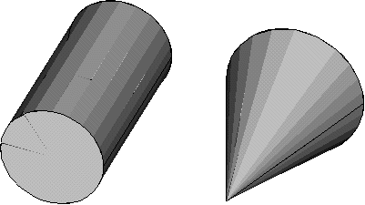
Building your model from the top down: The Mechanical APDL program also gives you the ability to assemble your model using geometric primitives, which are fully-defined lines, areas, and volumes. As you create a primitive, the program automatically creates all the "lower" entities associated with it. If your modeling effort begins with the "higher" primitive entities, you are said to be building your model "from the top down." You can freely combine bottom up and top down modeling techniques, as appropriate, in any model. Remember that geometric primitives are built within the working plane while bottom up techniques are defined against the active coordinate system. If you are mixing techniques, you may wish to consider using the CSYS,WP or CSYS, 4 command to force the coordinate system to follow the working plane.
Note: Solid modeling operations in a toroidal coordinate system are not recommended. Areas or volumes generated may not be what you expect.
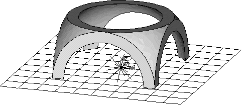
Using Boolean operators: You can "sculpt" your solid model using intersections, subtractions, and other Boolean operations. Booleans allow you to work directly with higher solid model entities to create complex shapes. (Both bottom up and top down creations can be used in Boolean operations.)
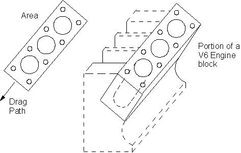
Dragging and rotating: Boolean operators, although convenient, can be computationally expensive. Sometimes a model can be constructed more efficiently by dragging, or rotating.
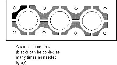
Moving and copying solid model entities: A complicated area or volume that appears repetitively in your model need only be constructed once. It can then be moved, rotated, and copied to a new location on your model. You might also find it more convenient to place geometric primitives in their proper location by moving them, rather than by changing the working plane.
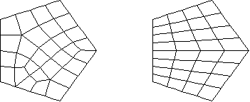
Meshing: Your ultimate objective in building a solid model is to mesh that model with nodes and elements. Once you have completed the solid model, set element attributes, and established meshing controls, you can then turn the Mechanical APDL program loose to generate the finite element mesh. By taking care to meet certain requirements, you can request a "mapped" mesh containing all quadrilateral, all triangular, or all brick elements.
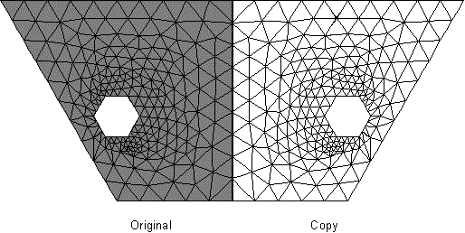
Moving and copying nodes and elements: Automatic meshing is a huge improvement over direct generation of nodes and elements, but it can sometimes be computationally time consuming. If your model contains repetitive features, you might find that the most efficient approach to model generation would be to model and mesh a pattern region of your model, then generate copies of that meshed region. (Copying a mesh in this manner will generally be faster than separately meshing repeated features.)
Solid model loads: In the Mechanical APDL program, loads are normally associated with nodes and elements. However, using solid modeling, you will often find it inconvenient to define loads at nodes and elements. Fortunately, you may assign loads directly to the solid model. When you initiate the solution calculations (with a SOLVE command), the program will automatically transfer these solid model loads to the finite element model.
Revising your model (clearing and deleting): Before you can revise your model, you need to be aware of the hierarchy of solid model and finite element model entities. A lower order entity cannot be deleted if it is attached to a higher-order entity. Thus, a volume cannot be deleted if it has been meshed, a line cannot be deleted if it is attached to an area, and so forth. If an entity is attached to any loads, deleting or redefining that entity will delete the attached loads from the database. The hierarchy of modeling entities is as listed below:
| Highest | Elements (and Element Loads) |
| Nodes (and Nodal Loads) | |
| Volumes (and Solid-Model Body Loads) | |
| Areas (and Solid-Model Surface Loads) | |
| Lines (and Solid-Model Line Loads) | |
| Lowest | Keypoints (and Solid-Model Point Loads) |
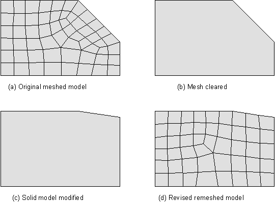
If you need to revise a solid model after it has been meshed, you must usually first delete all the nodes and elements in the portion of the model to be revised, using the xCLEAR commands. Once the solid model is cleared, you can delete (from the top down) and redefine solid model entities to revise your model.
As an alternative to clearing, deleting, and redefining, you can sometimes consider modifying the keypoints directly with the KMODIF command. By using KMODIF, you automatically clear and redefine the attached lines, areas, and volumes. After you have revised your solid model, you will need to remesh the portions that were cleared.


