


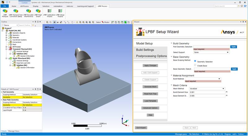
In the Model setup step:
Identify geometries of the part(s), supports, and base plate. Use Advanced Options for the simulation of powder or non-build items (such as clamps, bolts, etc.), or if you want to take advantage of symmetry.
Select your material. Use Advanced Options if the base plate or non-build items are a different material than the build material.
Set mesh criteria, such as type and sizing.
Action buttons are described in the following table.
| Action Button | Function | Action Button | Function |
|---|---|---|---|
Apply Changes
 | Click to apply the actions for this wizard step, which updates the project tree.
If you make additional changes, click Apply Changes again. Alternatively, you may choose to fill in the wizard fields for each step without clicking Apply Changes and then click Finish on the last step to execute all actions simultaneously. | Advanced Options | Click to toggle on/off options for materials, supports, and advanced geometry items of non build, powder, and symmetry. |
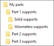
Add / Edit Support | Click to import the new support(s), or edit the selected
support(s), to the project tree. This action is separate from the Apply Changes button to allow the possibility of using multiple folders of support files. | Help | Click to bring up help for this wizard step. |
Delete Support | Click to delete the selected support(s) from the project tree. | Next | Click to move to the next wizard step. All required inputs on this step must be
filled in to be able to move to the next step. If the button does not appear blue, not
all required inputs are filled in. No actions are performed when you click Next. At times, you may want to fill out all the wizard inputs completely before applying any actions. Clicking Next without first clicking Apply Changes allows you to do that. |
Generate Mesh | Click to generate the mesh using the mesh criteria and to generate the
appropriate contact connections. Important: Be sure to click Apply Changes first before generating the mesh. This ensures the additive bodies (part/support/base plate) are identified correctly and a layered mesh will be generated. This action is separate from the Apply Changes button because meshing may take several minutes for large models. Sometimes users prefer to wait before generating the mesh. If you make changes to mesh criteria, click Apply Changes first and then Generate Mesh. | Back | Not applicable for this step. |
Read from Tree | Click to read the status of objects in the project tree and update the wizard
input fields accordingly. Think of this as the opposite action of Apply Changes, which
updates the objects in the project tree with inputs from the wizard. The status of the tree is read only from certain relevant tree objects. Advanced custom settings, such as complex mesh or contact settings, are not read from the tree and may be overwritten by the wizard upon a subsequent Finish click. It is best to make advanced custom tweaks after exiting from the wizard. See Recommended Workflow and Best Practices. | Exit Wizard | Click to exit the wizard. Any actions you have performed using Apply Changes will be maintained in the project tree. No additional actions will be performed upon exit. |
| Load Template | Click to load a previously saved template of wizard inputs.
You will still need to click Apply Changes or Finish, as usual. The setup items saved on the xml file include materials, mesh settings, build settings, and postprocessing selections. Geometry selections and advanced options involving geometry selections/picks are not included in saved files. Use Save Template in the Postprocessing Options step to save a template. |
Input fields are described in the following table.
| Input Field | Description | Example |
|---|---|---|
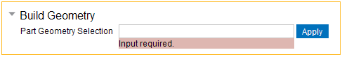
| Build Geometry: Part Geometry Selection
| Select the body representing the part you are manufacturing. Then click Apply.
Use Ctrl-click to select multiple bodies. The body should be a closed volume (watertight), and should be oriented with the global Z axis as the build direction. It may be modeled either resting on the base plate (Z=0), or elevated off the base by supports. See additional guidelines, including information about topology and symmetry. Affects these tree objects: AM Process, creates BUILD named selection |  |
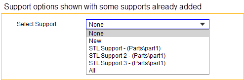
| Select Support
| Choose None if the part
is resting on the base and no other supports are in the model. Choose New to add a support, which opens the Support Type options. Choose one individual support, or All, followed by clicking the Delete Support button, to delete one or all supports in the model. (Selecting more than one but fewer than all supports is not possible at this time.) When deleting a Predefined Support, the geometry body will remain in the tree but the Predefined Support definition will be deleted. Note that even suppressed supports appear in the selection dropdown and can be edited or deleted, although you cannot suppress or unsuppress supports from within the wizard. Affects these tree objects: AM Process, Support Group, STL Support, Predefined Support, Generated Support. | |
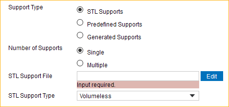
| Support Type - STL Supports
| Choose STL Supports if
you have support structures saved in .stl files that were not imported along with the
part geometry. Important: STL support files must be in millimeters. Number of Supports:
STL Support Type:
Click Add / Edit Support to import the file(s) and see the supports. See additional information about supports. Affects these tree objects: Support Group, STL Support | 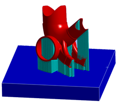 |
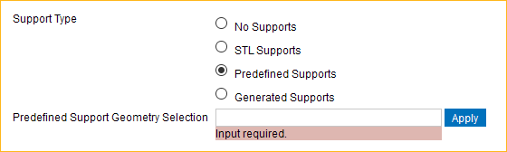
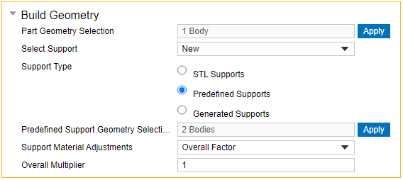
| Support Type - Predefined Supports
| Choose Predefined Supports if you have solid
support bodies that were imported with your part geometry. Select the body and click
Apply. Use Ctrl-click to select multiple bodies. Click Advanced Options if you want to make material adjustments to the supports. Affects these tree objects: Predefined Support | 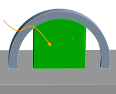 |
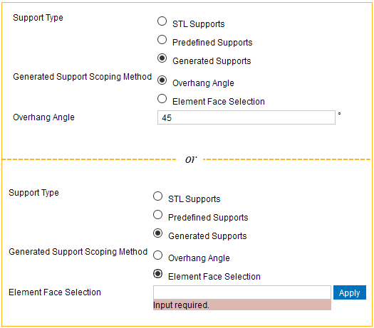
| Support Type - Generated Supports
| Choose Generated Supports to have the Mechanical
application generate supports directly as elements with no associated geometry.
Elements are generated straight down from the part mesh by either automatic detection
based on the Overhang Angle criterion or from mesh element faces that you select on
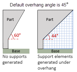
the part. Because this type of support is generated from an existing mesh, you first must have a mesh established for the part and base in order to apply a Generated Support. Select the part and base with Support Action set to None, add appropriate mesh criteria, click Apply Changes, then click Generate Mesh. After the basic AM process is set up using the above method, select the Support Action to Add Support and the Support Type to be Generated Support, and then proceed to identify how and where the supports will be generated by choosing either Overhang Angle or Element Face Selection. Then click Apply Changes to see the generated elements. Overhang Angle: Enter the angle measured from the horizontal base plate (0 degrees) to the surface of the part. Any surface measuring less than the Overhang Angle will be supported. Elements are generated vertically straight down from the overhanging portion of the build to the base, or to a lower portion of the model if it is in the way. Default is 45°.
Element Face Selection: In the graphics window, select the element faces of the part mesh from which support elements will be generated straight down. Click and drag to select multiple element faces. Then click Apply in the wizard. Notes:
Affects these tree objects: Generated Support | 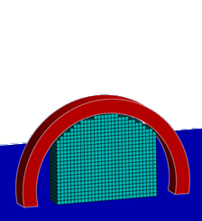 |
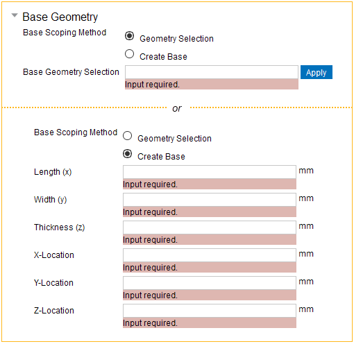
| Base Geometry
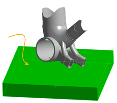
| Select the base body and click Apply. This is the platform on which the build
(part plus supports) is to be printed. It is included in the simulation because it
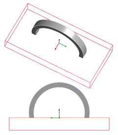
acts as a heat sink. Choose Create Base if none was included with your part geometry import. Enter overall dimensions of the body and coordinates from the center of the top of the base body. A red outline will guide you as you create the base. Use pan, zoom, and rotate mouse options to view the base preview from all angles. If you choose Create Base and you do not have STL Supports, base sizing is automatic. The wizard generates one that is appropriately sized and positioned for your model. Internally, the application reads the bounding box coordinates of all your build geometries and sizes the base plate to twice the dimensions in the X-Y plane and with an appropriate thickness starting at the minimum Z coordinate. Note that base creation does not take into account any STL Support dimensions so you may have to adjust the minimum Z-location depending on the STL Support. Affects these tree objects: AM Process, creates BASE named selection, and Construction Geometry if you created a base | Selecting a base
Creating a base
|
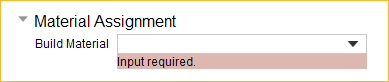
| Material Assignment
| Select the desired material from the drop-down list of
Ansys-supplied sample additive materials. Both the build and the base are assigned the same material by default. Click Advanced Options if you want to designate a different material for the base. By default, nonlinear effects are turned on in the simulation. Click Advanced Options to turn off nonlinear effects. See additional information about materials. Affects these tree objects: Material assignment for each geometry component under Geometry | |
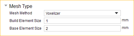
| Mesh Criteria - Mesh Method = Voxel
| Choose Voxelizer to create a mesh of cubic
elements for the geometry. Small features, curved surfaces, and horizontal or vertical
surfaces that are not multiples of the mesh size are automatically accounted for by a
knock-down factor technique. Note: The voxelizer mesh method is not available on a
Linux platform. Build Element Size is the edge length of the cubic elements of the part and support mesh, which defines the super layer height. Base Element Size is the edge length of the elements of the base mesh. See additional information about mesh controls. Affects these tree objects: Mesh Method renamed to Part Voxelizer, Mesh Sizing renamed to Base Sizing. After mesh generation, creates Build contact element faces and Base contact element faces named selections and Build to Base contact. | 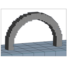 |
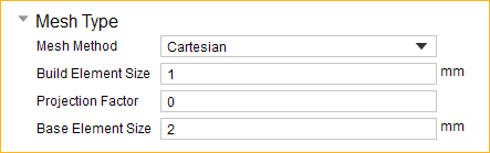
| Mesh Criteria - Mesh Method = Cartesian
| Choose Cartesian to create a hex mesh that
approximates the geometry. Small features, curved surfaces, and horizontal or vertical
surfaces that are not multiples of the mesh size are not captured accurately unless a
small mesh size is used. Build Element Size is the edge length of the hex elements of the part and support mesh, which defines the super layer height. Projection Factor defines how well the mesh will fit to the geometry. A value of 0 (default) results in cubic elements with a rough fit to the geometry. Increasing the Projection Factor will change the shape of the elements to better fit the geometry and may yield better results in some cases but may also result in a failed mesh. Our recommendation is to leave it at 0, or close to 0, initially and then iterate from there to see the effects of changing Projection Factor. Base Element Size is the edge length of the elements of the base mesh. Affects these tree objects: Mesh Method renamed to Part Cartesian, Mesh Sizing renamed to Base Sizing. After mesh generation, creates Build contact element faces and Base contact element faces named selections and Build to Base contact. | 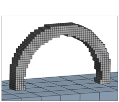 |
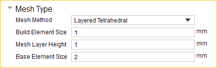
| Mesh Criteria - Mesh Method = Layered
Tetrahedral
| Choose Layered Tetrahedral to create an
unstructured tetrahedral mesh in layers based on a specified layer height fit to the
geometry. It captures the geometry well, and is useful if there are organic curves,
small features, such as holes, or thin-walled parts. Note: Generated Supports are not
available when using Layered Tetrahedral mesh method. Build Element Size is the triangle edge length of the elements of the part and support mesh. It can be greater than the Mesh Layer Height to allow the mesher to produce elements that are skewed with a longer direction parallel to the element layers. Mesh Layer Height is the height of each element layer, sometimes referred to as the super layer. Actual metal powder deposit layers are aggregated into finite element "super layers" for simulation purposes. Base Element Size is the edge length of the elements of the base mesh. Affects these tree objects: Mesh Method renamed to Part Layered Tetrahedral, Mesh Sizing renamed to Base Sizing. After mesh generation, creates Build contact element faces and Base contact element faces named selections and Build to Base contact. | 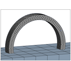 |
| Advanced Options | ||
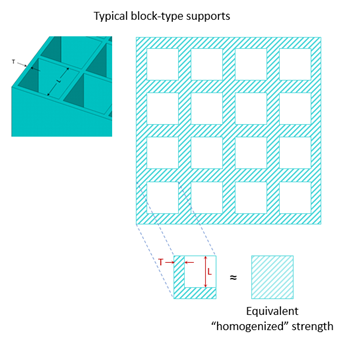
| Build Geometry, Predefined Supports and
Generated Supports
| In additive machines, supports are printed with the same material as the part but
as thin walled structures with less mass than the part. In the simulation we model the
supports as an equivalent "homogenized" solid rather than as thin-walled structures.
Their properties will be scaled down to account for this homogenization technique.
Affected properties are elastic modulus, shear modulus, yield strength, density, and
thermal conductivity. Select from one of the following methods for Support Material Adjustments for the Predefined/Generated Supports:
These properties can be changed after a support is added by changing the values and clicking Add / Edit Support. |
 |
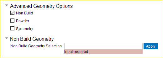
| Advanced Geometry Options, Non Build
| Choose Non Build to simulate geometry items that
are present on the base plate but that are not being 3D-printed. These items may
include clamps, bolts, measuring devices, instrumentation, etc. Select the body representing the non build component. Use Ctrl-click to select multiple bodies. Selecting the Non Build option will also make the field for the Non Build Element Size visible under Mesh Criteria. Affects these tree objects: Will create a named selection for non build elements, and a mesh sizing object for the selected non build geometry | 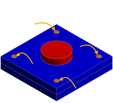 |
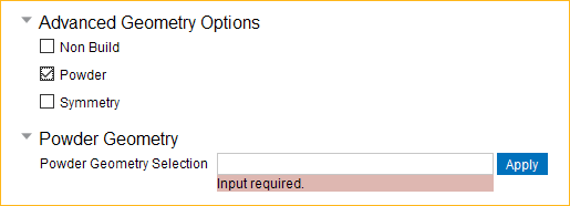
| Advanced Geometry Options, Powder
| Choose Powder to select a geometry body that
represents unmelted powder. Modeling the powder as elements may be useful if you are
simulating multiple parts close together on the build plate or if the part has
features close together, where accounting for the heat transfer occurring between the
parts or features is important. Select the body representing the powder and click Apply. Use Ctrl-click to select multiple bodies. The mesh size for this will be the same as the build mesh size in order to have the same layer height. See additional information about modeling powder. Affects these tree objects: Will add a powder elements named selection for the selected powder geometry. | 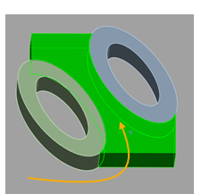 |
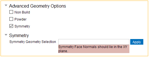
| Advanced Geometry Options, Symmetry
| Choose Symmetry if your model has symmetrical
geometry—specifically, if it is symmetric with respect to the part, supports,
and build plate, and it has symmetric loading and
boundary conditions. Simulating a sector of a large model will result in a faster
simulation time while using fewer resources. Select the faces representing the symmetry plane and click Apply. Use Ctrl-click to select multiple faces. See additional information about modeling symmetry. Affects these tree objects: Will add a SYMM_NODES named selection and a Symmetry Region object | 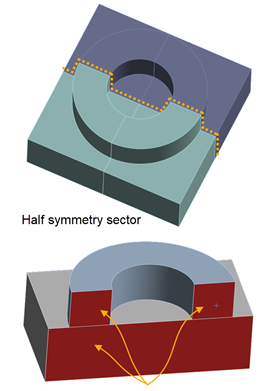 |
The next step of the wizard is Build Settings. The procedure varies depending on whether you have a Thermal-Structural system or an Inherent Strain system: