


Go directly to procedural steps.
Typically, you’ll have these geometric bodies in the simulation model:
Part – This is the part you are manufacturing. It should be a closed volume (that is, watertight), and should be oriented with the global Z axis as the build direction. It may be modeled either resting on the base plate (Z=0), or elevated off the base plate by supports.
The part can be made of multiple bodies but must have boundaries that are aware of each other in order to assure a proper conformal mesh throughout the part. A conformal mesh is one where the elements fit together seamlessly along their shared boundaries or faces. In other words, there are no gaps or overlaps between adjacent elements. This is achieved through either shared topology, a voxelization mesh option, or AM Bond connections, depending on your meshing approach, as described in the meshing step.
If your model exhibits symmetry, you can simulate a sector of a large model to achieve a faster simulation time. See Modeling a Symmetrical Part for more details.
Usually only one part is simulated even if there will be many duplicate parts nested on the base plate for efficiency. (A multiplier on the build time should be used if this is the case, as described in Machine Settings.)
Support Structures – Supports are needed to anchor overhanging part features so they do not break away from the platform during the 3D print process because of residual stress buildup. Overhanging features are usually those with angles less than 45° to the horizontal X-Y plane. Supports may be modeled in several ways. Together, the part and supports constitute the build.
Base Plate – This is the platform on which the build (part plus supports) is to be printed. It is included in the simulation because it acts as a heat sink.
Other geometric bodies that may be simulated include:
Powder – Modeling the powder may be useful if you will be simulating multiple parts close together on the build plate or if the part has features close together, where accounting for the heat transfer occurring between the parts or features is important. Create a separate, closed-volume (watertight) body to represent the powder in-between multiple parts or in-between features of the same part. Details of how to model powder in the simulation are found in Advanced Topics.
Non-build Components – At times you may want to simulate geometry items that are present on the build plate but that are not being 3D-printed. These items may include clamps, bolts, measuring devices, instrumentation, etc. They may influence the heat dissipation and/or distortion of the part being built so they need to be included in the simulation. Details of how to model non-build components are found in Advanced Topics.
For your part geometry, commonly imported file types include SpaceClaim .scdoc files (non-faceted) and stereolithography .stl files (faceted). For other options, see Attach Geometry/Mesh in the Mechanical User's Guide.
You may create the base plate and supports ahead of time in the CAD program or in a support generation tool, or wait to create those bodies in the Mechanical application (described in subsequent steps). If supports are created in CAD, the part and support bodies should be kept as separate bodies (that is, not merged) so that they can be distinguished as such in the AM simulation in Mechanical. Whether you set the bodies to "share topology" in the CAD program depends on whether you will be using a Cartesian mesh, a Cartesian mesh with voxelization option, or a layered tetrahedrons mesh in the simulation in Mechanical. For a discussion about this topic, see To Share Topology or Not?. When everything is imported into Workbench, you will later identify the support bodies as predefined supports.
Alternatively, you may choose to not include supports when you attach the part but import the supports separately later as .stl files.
Note: Working with a model with supports from Additive Prep—When you have created your model for AM simulation that includes generated supports in Additive Prep:
If you used the recommended transfer to Workbench feature, the geometry is already attached and you can skip the first step in the procedural steps below.
If you did not use the recommended transfer to Workbench feature and instead opened Mechanical directly with a saved .scdoc file:
Mechanical recognizes the file as an AM file and launches with the AM Process object and STL Supports automatically populated. If you had not joined the individual supports together into one support for each part, they will be imported as many individual stl supports and it may be unmanageable to continue on for simulation.
With the AM Process object already in place, the LPBF Setup Wizard cannot be used to set up this simulation. Continue setting up the simulation manually in the project tree.
Procedural Steps
Right-click the Geometry cell of the Transient Thermal analysis block, and select Import. Browse for your file and import it. (Double-clicking on the Geometry cell opens SpaceClaim.)
After importing geometry, double-click the Model cell (or right-click, and select Edit) of the Transient Thermal analysis block to launch the Mechanical application. It may take a few minutes for Mechanical to open and your geometry to appear in the Geometry window. (In addition to the Workbench icon,
 , in the taskbar, note the
 icon once Mechanical opens;
there are now two applications open.)
icon once Mechanical opens;
there are now two applications open.)Once your geometry is loaded in Mechanical, review how it is presented in the project tree.
We will use an example model to be simulated that includes an arch part and a solid support as separate bodies comprising the build, and the base plate as another separate body.
Recall that there are different requirements for connectedness of geometric bodies depending on the mesh method you will use:
A Cartesian mesh method requires shared topology between the part and predefined supports.
A Cartesian mesh method with the voxelization option may have shared or unshared topology between the part and predefined supports.
A layered tetrahedrons mesh method requires that there be no shared topology (that is, unshared topology) between the part and predefined supports.
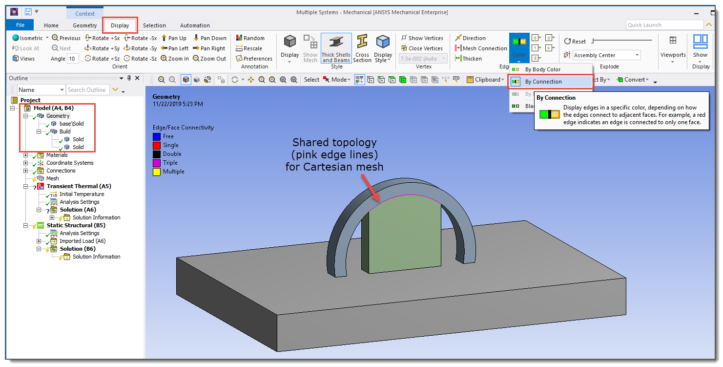
To check whether your geometry has shared topology, click the Display tab and in the Edge group, choose Color and then choose By Connection from the drop-down menu. Pink edges means that an edge is shared by three faces which is an indication of shared topology.
In the arch with support example, the geometry in the first figure was imported from SpaceClaim with shared topology. First notice the structure of the bodies in the project tree. The arch part and support bodies are child objects under Build. Also, in the Graphics Window, note the pink edges at the body interfaces when Edge Coloring > By Connection is turned on. We will mesh this model with a Cartesian mesh method (without using the voxelization option).
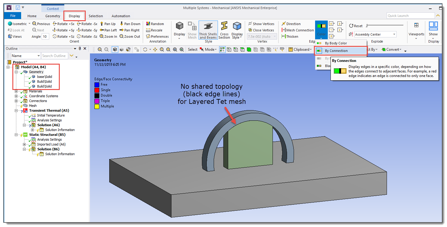
The geometry in the next figure was imported from SpaceClaim with unshared topology. Notice how the bodies are shown as independent bodies in the project tree, not as child objects under the Build object. Also, there are no shared edges between bodies (lines are black instead of pink), indicating there is no shared topology. We will mesh this model with a layered tetrahedrons mesh method.
Once the Mechanical application opens, it is a good time to adjust the number of processors (cores) you are using on your computer. Depending on the complexity of your model, AM Process Simulations may be computer intensive. If you have an Ansys HPC license, access the option in the Solve group on the Home tab and change the Cores to something appropriate for your simulation.