Go directly to procedural steps.
The layer-by-layer additive printing process is simulated with element layers added one-by-one using the element birth/death technique. As such, the mesh must have a uniform size in the build (global Z) direction. That is, each element layer must have the same height (constant Z coordinate).
For the build, we recommend using one finite element "super layer" of elements to represent 10-20 actual metal powder layers. If your machine has a 25-micron powder layer thickness (also called deposition thickness), your element size should be between 0.25 and .5 mm. The element sizing does not have to be an even multiple of the deposit layer thickness. Note that the real machine build time is approximately the transient thermal build step simulation time multiplied by R^(1/3), where R is the number of deposit layers in one element layer. (This estimate of the real build time is provided for you in the simulation results.)
A much coarser mesh is acceptable for the base plate because it is simply serving as a heat sink and a fixed support in the simulation.
Three primary meshing methods/options are available for additive manufacturing process simulation, each with their strengths and weaknesses.
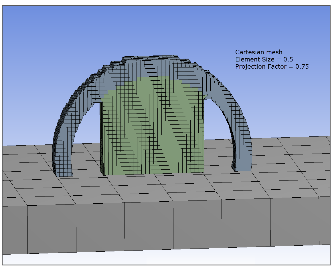
The Cartesian Mesher creates a hex mesh that approximates the geometry. Small features, curved surfaces, and horizontal or vertical surfaces that are not multiples of the mesh size are not captured accurately unless a small mesh size is used. The method is fast and, for most distortion and residual stress predictions, is quite adequate.
The Mechanical application can automatically generate supports when a part has a Cartesian mesh. (See Generated Supports in the next step.)
The Cartesian Mesher with the voxelization option creates a voxel (cubic element) mesh for the geometry. Small features, curved surfaces, and horizontal or vertical surfaces that are not multiples of the mesh size are accounted for by a knock-down factor technique.
Limitations with the voxelization option:
The voxelized mesh option (Cartesian Mesh with Voxelization Option) is not available on a Linux platform because the underlying voxelizer code is incompatible with Linux. Choose between a Cartesian mesh and a layered tetrahedrons mesh.
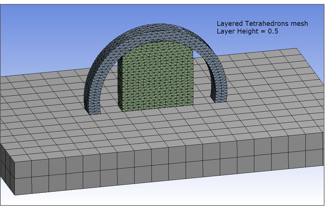
The Layered Tetrahedrons Mesher creates a tetrahedrons mesh that conforms to a specified layer size. It captures the geometry well, and is useful if there are organic curves, small features, such as holes, or thin-walled parts.
Limitations with the layered tetrahedrons mesher:
Bodies with shared topology cannot be meshed with the layered tetrahedrons mesher. We recommend you separate bodies into individual parts in CAD. (Use Unshare in SpaceClaim or Explode Part in DesignModeler to do this.) See To Share Topology or Not?.
The AM octree adaptive meshing method is not supported for parts meshed with layered tetrahedrons.
Auto-generated supports are not available for parts meshed with layered tetrahedrons. You should bring supports in with your geometry as predefined supports or as a separate .stl file.
The model should not have other suppressed bodies.
The mesh is not associated back to the geometry.
This method cannot be used in conjunction with mesh controls such as Inflation, Refinement, Match Control, Pinch, Face Meshing, Face Sizing, and Edge Sizing controls.
Procedural Steps
We will describe the meshing steps using the arch with support model for both the Cartesian and layered tetrahedrons mesh techniques.
Using a Cartesian Mesh
Set mesh controls for the part and support bodies. The size of the mesh is required to be the same throughout all bodies in the build. Remember that the build requires a finer mesh than the base plate.
To set mesh controls for the build, we will use a meshing shortcut designed for AM Process Simulations. In the project tree, select the AM Process object and then select the Cartesian Control option from the ribbon (AM Process context tab). Or, right-click the AM Process object and select Insert > Cartesian Mesh. Notice that a Body Fitted Cartesian object has appeared under the AM Process object and become active and that all the bodies that are part of the build are selected.
In Details of the Body Fitted Cartesian object, under Definition, set the Element Size to the desired value. (Click in the right column on the word Default to activate the text field.)
Under Advanced, you may choose to set the Projection Factor slider to a value between 0 and 1. The Projection Factor defines how well the mesh will fit to the geometry. A value of 0 (default) results in cubic elements with a rough fit to the geometry. Increasing the Projection Factor will change the shape of the elements to better fit the geometry and may yield better results in some cases but may also result in a failed mesh. Our recommendation is to leave it at 0, or close to 0, initially and then iterate from there to see the effects of changing Projection Factor.
You can apply a Coordinate System for the mesh. Typically, the default global coordinate system is appropriate but you may want to set it to one located on the top surface of the base plate.
For additional information about Cartesian meshes, see Cartesian Method Control in the Meshing User's Guide.
Set mesh controls for the base plate. Highlight the Mesh object and right-click Insert > Sizing. A Sizing object is created under the Mesh object and becomes active.
Select the base plate body and hit Apply in the Details view.
Under Definition, change the Element Size to the desired value, something that will result in a fairly coarse mesh.
Finally, highlight the Mesh object and right-click Generate Mesh. If you don't like the generated mesh you can easily go back and change element sizes, then right-click Mesh and select Update.
Using a Cartesian Mesh with Voxelization Option
First, set mesh controls for the part and support bodies. The size of the mesh is required to be the same throughout all bodies in the build. Remember that the build requires a finer mesh than the base plate.
To set mesh controls for the build, we will use a meshing shortcut designed for AM Process Simulations. In the project tree, select the AM Process object and then select the Cartesian Control option from the ribbon (AM Process context tab). Or, right-click the AM Process object and select Insert > Cartesian Mesh. Notice that a Body Fitted Cartesian object has appeared under the AM Process object and become active and that all the bodies that are part of the build are selected.
In Details of the Body Fitted Cartesian object, under Definition, set the Mesh Using Voxelization option to Yes. (This option is set to No and is grayed out on a Linux operating system.)
Under Advanced, set the Element Size to the desired value.
Adjust the Wall Thickness, as needed, according to the single-bead thickness set by your machine.
Adjust the Subsample Rate, as needed. For most cases, we recommend using the default value of 5.
The part will be meshed with cubic elements. Each cubic element is divided into sampling regions to determine density of material within that element. These are used as material property knockdown factors. A Subsample Rate of 5 (default) = 5 x 5 x 5 = 125 subdivisions. Subsample Rate affects the accuracy of element density.
Next, set mesh controls for the base plate. Highlight the Mesh object and right-click Insert > Sizing. A Sizing object is created under the Mesh object and becomes active.
Select the base plate body and hit Apply in the Details view.
Under Definition, change the Element Size to the desired value, something that will result in a fairly coarse mesh.
Finally, highlight the Mesh object and right-click Generate Mesh. If you don't like the generated mesh you can easily go back and change element sizes, then right-click Mesh and select Update.
Important: The mesh generated using the voxelization option is not fully associated to the part geometry. Loads scoped to the part body (face, edge, vertex) are not possible. However, loads scoped to the mesh of the part (that is, FE loads) are valid. These can be defined with named selections or manual selection.
As a best practice when using the voxelizer mesh method, select all build bodies at one time for a single mesh operation. This includes part bodies, Predefined Supports, and powder bodies, if any. As a result of the single voxel mesh operation, conformal mesh will be created among all bodies and contact connections between them will not be needed. If each geometry has its own voxel mesh method object, then you will need to define AM Bond connections or contacts between them.
Consider using AM octree adaptive meshing to reduce simulation time if your part has bulky or blocky areas, especially near the bottom (that is, near the lower layers). The AM octree method of nonlinear mesh adaptivity coarsens the mesh in previously deposited layers, resulting in a reduction in total element count. The method is only available for parts that have been voxelized. See Using AM Octree Adaptive Meshing.
Using a Layered Tetrahedrons Mesh
To use a layered tetrahedrons mesh, in Ansys Mechanical:
Click Mesh in the Tree Outline, right-click and select Insert > Method. Select the build geometry—use the Ctrl key to select multiple bodies, for example if you have part and predefined support bodies—and in Details view, click Apply. In Details under Definition, change the Method to Layered Tetrahedrons.
In the Layered Tetrahedrons Details view, set the Layer Height as desired. Note that the layer height should balance the need to capture features and the need for a reasonable simulation run time. The recommended setting for this "super layer" is 10-20 times the size of the machine deposition thickness.
Most of the remaining advanced settings in the Details view have adequate defaults.
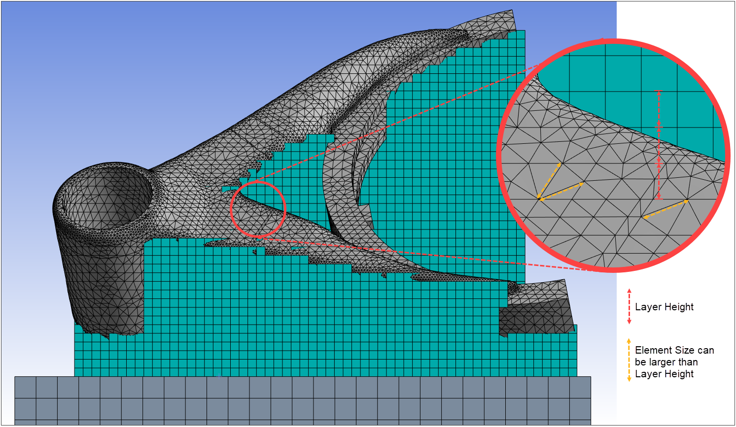
Click the Mesh object, and in its Details view, set the Element Size. Element Size can be less than, equal to, or greater than the Layer Height but should not be greater than 6 times the Curvature Min Size. Consider starting with an initial value slightly larger than Layer Height. This allows individual elements to have non-Z-direction edge lengths longer than Layer Height while still keeping the overall Z-direction height at Layer Height.
Initially, use the default settings for the remaining options. The default settings are customized for additive process simulations only when the AM Process object is in the project tree so it is always best to add the AM Process object before meshing. Review the following global mesh settings and change them as necessary:
Defaults Element Order Quadratic (default if the AM Process object is in the project tree). Note that mid-noded elements will be generated, but the mid-nodes will be kept straight and will not conform to the geometry. Element Size Can be greater than Layer Height. The Element Size should not be greater than 6 times the Curvature Min Size specified. The mesh quality reduces as the Element Size / Curvature Min Size ratio increases. Sizing Use Adaptive Sizing No (default if the AM Process object is in the project tree) Capture Curvature Yes (default if the AM Process object is in the project tree) Curvature Min Size Dynamically calculated to be 0.3 times the Layer Height (specified in Details of Layered Tetrahedrons mesh method object). Used by the mesher to generate a surface mesh before the slice layers are generated, hence this min size drives the resolution of the mesh. The min size should be decided based on the features that are to be resolved and the Layer Height. A recommended value is 1/4 to 1/3 of the Layer Height. Curvature Normal Angle 27 (default if the AM Process object is in the project tree). The recommended range is 18 to 36. Use a lower angle if the model has small features like holes and fillets that you want to preserve. Defeature Size Dynamically calculated to be 10% of the Curvature Min Size. Used to define the default value for sliver face height. Based on the model, you might be required to increase it. We do not recommend using a value greater than one-half of the Curvature Min Size. Understanding the approach that the layered tetrahedrons mesher uses may be useful if you are not satisfied with the meshes being generated. After experimenting with the mesh settings described here, if you are still not happy with the tetrahedrons mesh, consider adjusting Relative Tolerance, Inflate Relative Tolerance, and Sliver Triangle Height. Care must be taken to ensure that the layer slices cut the geometry in such a way as to avoid thin slices. Thin slices may cause the mesher to struggle or result in poorly shaped elements. Usually adjusting the mesh Layer Height or increasing Relative Tolerance will lead to a higher quality mesh. Refer to the Layered Tetrahedrons Method Control in the Meshing User's Guide for further information.
Next, set mesh controls for the base plate that will produce a much coarser mesh. Highlight the Mesh object and right-click Insert > Sizing. A Sizing object is created under the Mesh object and becomes active.
Select the base plate body and hit Apply in the Details view.
Under Definition, change the Element Size to the desired value, something that will result in a fairly coarse mesh.
Finally, highlight the Mesh object and right-click Generate Mesh. If you don't like the generated mesh you can easily go back and change element sizes and settings, then right-click Mesh and select Update.