During a laser powder bed fusion (LPBF) process, almost all the heat dissipation is through the part and supports back to the build plate rather than out through the unmelted powder surrounding the part. Many users ignore the small effect of heat loss through powder but you may choose to model it in one of two ways:
As equivalent heat convection
By including powder elements as a named selection called POWDER_ELEMENTS. (For MAPDL users, use an element component CM,POWDER_ELEMENTS,ELEM).
Modeling the powder as elements may be useful if you will be simulating multiple parts close together on the build plate or if the part has features close together, where accounting for the heat transfer occurring between the parts or features is important. The following is an overview of the procedure:
In your CAD program, create a separate body to represent the powder in-between the parts or features. If you will be using a Cartesian mesh, share topology between the bodies. If you will be using a layered Tetrahedrons mesh, do not share topology.
In the Mechanical application, identify the build and base bodies on the AM Process object as usual. Do not select the powder body when identifying the build and base bodies.
Assign the same material property that you use for the build to the powder body.
Depending on your chosen mesh type, account for the connections between bodies and mesh the model.
Create a named selection, called POWDER_ELEMENTS, of elements associated with the powder body. This Ansys-defined named selection will use the knockdown factor, Powder Property Factor, identified in the Build Conditions to estimate the powder properties.
Proceed with the rest of the simulation as normal.
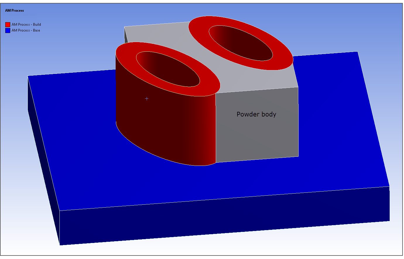
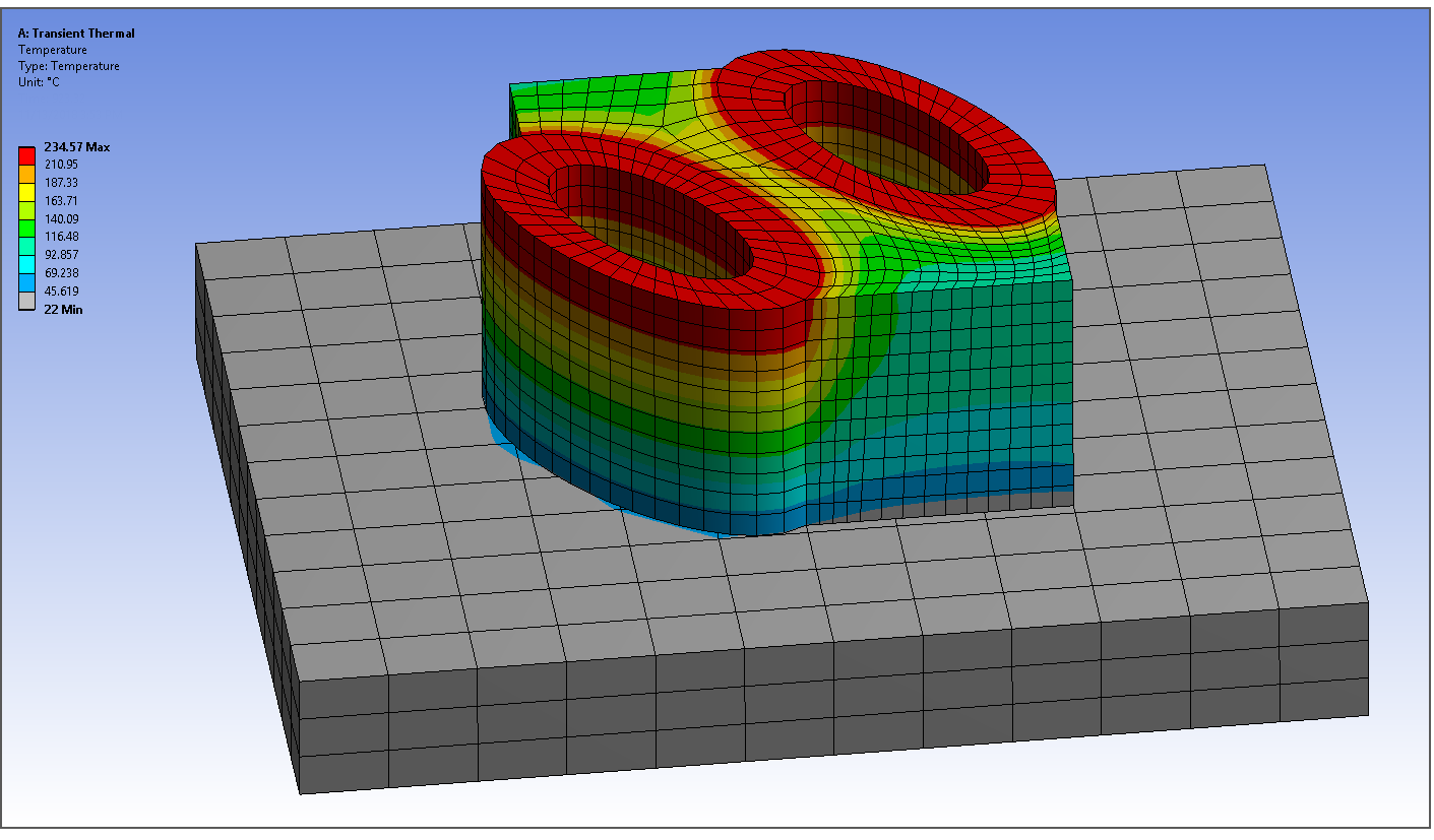
In the following example, the powder was modeled between two cylindrical parts close together on the build plate. Temperature contours are shown in the second figure. Notice the heat transfer in the powder area between the parts.