4.2. Wizard Step 2: Build Settings (for Inherent Strain Simulations)

In the Build Settings step:

  • Simulation assumptions are set by default based on your chosen AM LPBF system. Choose the Inherent Strain Definition.

  • Enter calibration factor(s) as determined from calibration experiments. Use default calibration factors if your goal is simply to examine trends, that is, the effects of variable changes on stress or distortion relative to each other.

  • Enter machine settings, which are process parameters that directly influence how the process deposits material. These can include Deposition Thickness, Hatch Spacing, Scan Speed, and a number of other factors.

  • Enter build conditions, which are settings pertaining to the environment around the part during the deposition process and during cooldown. This includes Preheat Temperature.
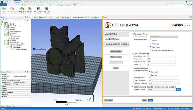
Action buttons are described in the following table.

Action ButtonFunctionAction ButtonFunction
Apply Changes
Click to apply the actions for this wizard step, which updates the project tree. If you make changes, click Apply Changes again.Help
Click to bring up help for this wizard step.
Read from Tree
Click to read the status of objects in the project tree and update the wizard input fields accordingly. Think of this as the opposite action of Apply Changes, which updates the objects in the project tree with inputs from the wizard. Next
Click to move to the next wizard step. All required inputs on this step must be filled in to be able to move to the next step. If the button does not appear blue, not all required inputs are filled in.

No actions are performed when you click Next.

At times, you may want to fill out all the wizard inputs completely before applying any actions. Clicking Next without first clicking Apply Changes allows you to do that.

Advanced Options
No advanced options for this step.Back
Click to go back to the previous wizard step.
Exit Wizard
Click to exit the wizard. Any actions you have performed using Apply Changes will be maintained in the project tree. No additional actions will be performed upon exit.

Input fields are described in the following table.

Input FieldsDescription
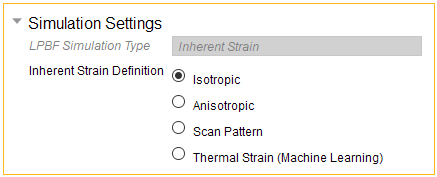
Simulation Settings


Choose one of the following strain definitions, which reflect how inherent strain is calculated as an input to the structural solver:
  • Isotropic assumes that a constant, uniform strain occurs at every location within a part as it is being built. This is the simplest assumption, resulting in the shortest simulation time.

  • Anisotropic subdivides the strain into anisotropic components in the X, Y, and Z directions based on the Global coordinate system.

  • Scan Pattern subdivides strain into anisotropic components based on the local orientation of scan vectors within the part. Scan vectors are generated internally via a slicing function assuming a rotating stripe scan pattern or input directly from a build file.

  • Thermal Strain (Machine Learning), using a Machine Learning prediction, is a method that provides the highest level of fidelity and takes thermal cycling into account at each location within the part. As with Scan Pattern, scan vectors are generated internally via a slicing function assuming a rotating stripe scan pattern or input directly from a build file.


    Important:  The Machine Learning Prediction feature requires a Structures AI+ license.


    Machine Learning Model is a list of materials that were used to train the ML prediction, in particular, the materials validated for the Additive application. Choose the material that most closely matches your material assignment in Engineering Data. ML models may be based on different material properties than those in Engineering Data. The ML models are used to generate loading strains. Materials in Engineering Data are used for the structural analysis.

Affects these tree objects: Build Settings

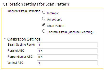
Calibration Settings


Enter strain scaling factors. These are optional inputs that scale the inherent strains by a given value. They are usually determined from calibration experiments and account for differences in materials, machines, and other factors.
  • Isotropic allows one Strain Scaling Factor reflecting uniform scaling in all directions. It defaults to 1.

  • Anisotropic allows a strain scaling factor for each global coordinate direction. These default to 1.

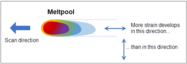
  • Scan Pattern and Thermal Strain allow strain scaling factors, called Anisotropic Scaling Factors, parallel and perpendicular to the scanning direction in the X-Y plane, and one that is vertical in the build direction. The default ASCs take into account the fact that more strain develops in the scan direction than perpendicular to it, with Parallel ASC = 1.5, Perpendicular ASC = 0.5, and Vertical = 1. You can also enter a uniform Strain Scaling Factor, which defaults to 1.


Affects these tree objects: Build Settings

Machine Settings


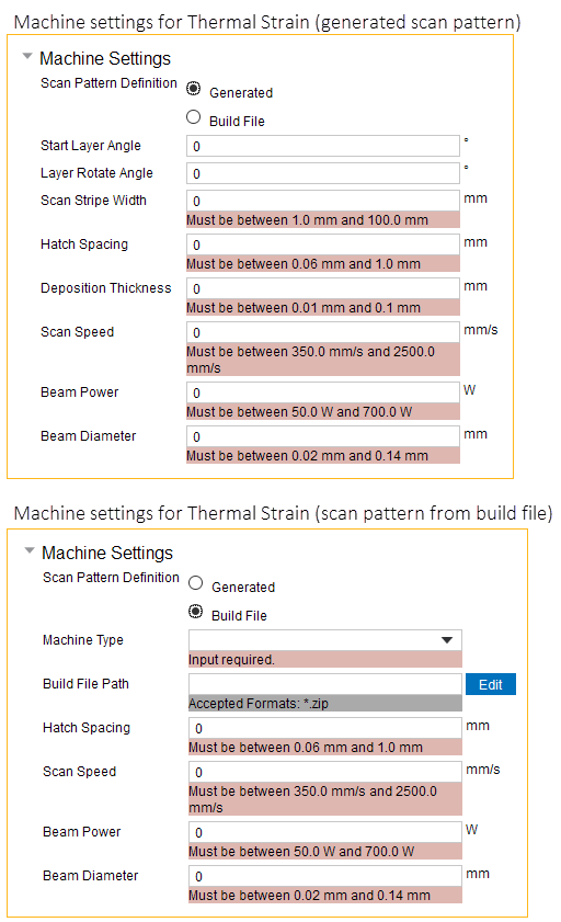
Enter the Machine Settings, which are settings and process parameters that directly influence how the process deposits material. Every simulation except isotropic uses some, or all, of these parameters:
  • Scan Pattern Definition is how the scan pattern is defined, either generated using a rotating stripe pattern (default) or input via a build file.

    Build File Path is the location of a .zip file containing the scan pattern file(s), and an stl of the part geometry. See Build File Requirements.

    Machine Type identifies the machine or OEM associated with the specified build file. Options are Additive Industries, EOS, HB3D, Renishaw, Sisma, SLM, and Trumpf.

  • Start Layer Angle is the orientation of fill rasters on the first layer of the part. It is measured from the X axis, such that 0 degrees results in scan lines parallel to the X axis. The starting layer angle is commonly set to 57 degrees. Must be between 0 and 180°.

  • Layer Rotation Angle is the angle at which the major scan vector orientation changes from layer to layer. It is commonly 67 degrees. Must be between 0 and 180°.

  • Scan Stripe Width is the width of the sections, called stripes, into which the geometry is sliced. The stripes are scanned sequentially to break up what would otherwise be very long continuous scan vectors. Slicing Stripe Width is typically set to 10 mm wide. Must be between 1 and 100 mm.

  • Hatch Spacing is the average distance between adjacent scan vectors when rastering back and forth with the laser. Hatch spacing should allow for a slight overlap of scan vector tracks such that some of the material re-melts to ensure full coverage of solid material. For Thermal Strain (Machine Learning) strain definition, must be between 60 and 1000 microns.

  • Deposition Thickness is the thickness of deposited material in every pass of the recoater blade. Specifically, use the amount the base plate drops between layers.

  • Scan Speed is the average speed at which the laser spot moves across the powder bed along a scan vector to melt material, excluding jump speeds and ramp up and down speeds. For Thermal Strain strain definition, must be between 350 and 2500 mm/sec and the recommended range is between 500 and 2500 mm/sec.

  • Beam Power is the power setting for the laser in the machine. Must be between 50 and 700 Watts. The recommended range is between 50 and 500 Watts.

  • Beam Diameter is the width of the laser on the powder or substrate surface defined using the D4σ beam diameter definition. Usually this value is provided by the machine manufacturer. Sometimes called laser spot diameter. Must be between 20 and 140 µm. The recommended range is between 80 and 120 µm.

Affects these tree objects: Build Settings

Build Conditions


Enter Build Conditions, which are settings pertaining to the environment around the part during the deposition process.
  • Preheat Temperature is the starting temperature of the build plate. Used when Inherent Strain Definition = Thermal Strain. Must be between 20 and 500 °C and the recommended range is between 20 and 200 °C.

Affects these tree objects: Build Settings

Base Structural Boundary Conditions


Select the face of the base where the fixed support should be applied, usually the underside of the base. Then click Apply. Use Ctrl-click to select multiple faces. By default, the underside surface of the base is already selected.

Affects these tree objects: Fixed boundary condition under Static Structural system